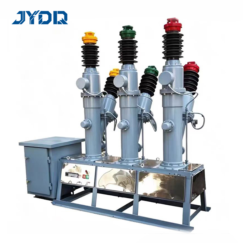
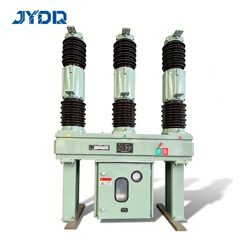
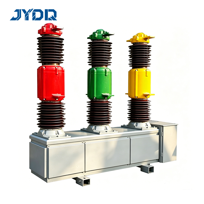
40.5KV, 35KV, 30KV Series SF6 Circuit Breakers: Overview
The 40.5KV, 35KV, 30KV Series covers outdoor SF6 circuit breakers designed for the upper tier of medium-voltage primary distribution, where rated voltage exceeds the conventional 10–24 kV range. In this voltage band, the LW Series SF6 breakers deliver reliable fault interruption and load switching for primary substations, regional grid nodes, and large industrial power supply applications where operational continuity is essential.
Using sulfur hexafluoride (SF6) as the arc-quenching medium, these outdoor breakers offer high dielectric strength and fast arc extinction suited for substation environments. Built on a self-developed SF6 operating mechanism with premium materials, they are available with customizable configurations to meet buyer-specific installation, climate, and grid authority requirements.
Key Product Characteristics
Voltage range: The 40.5KV, 35KV, 30KV Series covers rated voltages of 30 kV, 35 kV, and 40.5 kV within a single consistent product family, supporting systems from 30 kV primary substations to 40.5 kV grid connection points.
Breaking capacity: Short-circuit breaking current from 20 kA to 31.5 kA for utility feeders and industrial substations with transformer-fed bus systems and large motor loads. Load calculation electrical analysis at the installation point determines the required breaking capacity for each application.
Mechanical endurance: M2 mechanical endurance class per IEC 62271-100, suited to frequent operation cycles over a long service life in radial feeders, bus-tie switching, and automatic reclosing applications.
Capacitive switching: C2 capacitive switching class for line charging and capacitor bank switching without restrike risk—a requirement that must be confirmed during the specification phase, not post-commissioning.
Environmental adaptability: G1 and G2 climate variants for tropical, temperate, and subtropical deployment conditions, accommodating diverse ambient temperature and humidity profiles across target markets.
Mounting designs: Horn-type and side-mounted configurations to suit different substation structural layouts and space constraints.
Standards compliance: Certified to IEC 62271-100, with KEMA type test verification and CE certification on applicable models.
Customizability: Configurable to buyer-specific installation, environmental protection, and documentation requirements for local grid authority submissions.
Warranty: 10-year warranty backed by a premium-material SF6 operating mechanism for reliable long-term operation.
Common Applications
The 30–40.5 kV range addresses the upper boundary of medium-voltage distribution, where fault consequences are more severe and compliance documentation requirements are more rigorous than in lower-voltage systems. Typical deployment environments include:
Primary distribution substations: Grid entry points requiring robust fault interruption and switching. In utility and industrial substations with mv switchboard configurations, these SF6 circuit breakers serve as the primary protection element at the incoming bus level, providing the fault isolation that the mv switchboard arrangement depends on.
Regional grid nodes: 35 kV and 40.5 kV interconnection points in regional transmission and distribution networks across Asia, Europe, Africa, and the Middle East.
Large industrial facilities: Manufacturing campuses and heavy industrial parks with dedicated 35 kV or 40.5 kV incoming supply, where the circuit breaker protects both the supply connection and the internal mv switchboard distribution system.
Renewable energy grid connection: Solar, wind, and hydropower installations requiring grid-side fault interruption and C2 capacitive switching at the 35 kV or 40.5 kV point of connection.
Primary substations feeding 10 kV networks: In primary substations where the incoming bus feeds a 10kv transformer bank that supplies downstream 10 kV distribution, the primary circuit breaker provides protection and fault isolation for the 10kv transformer and the network it serves.
Energy storage installations: Grid-scale battery and renewable energy storage projects requiring high-reliability switching and protection at the 35 kV or 40.5 kV interconnection level.
How to Select the Right Configuration: A Decision Framework
When evaluating the 40.5KV, 35KV, 30KV Series for a specific project, the procurement decision is not simply about selecting the highest-rated option. Reliability is determined by how well configuration choices align with actual operating conditions—not by the rated ceiling alone. The 35 kV and 40.5 kV options may appear technically interchangeable for some applications; both framings are partially valid but neither is complete without knowing your system voltage, fault level, and protection coordination requirements.
Key evaluation dimensions:
Rated voltage: Match the breaker's rated voltage to your system's highest operating voltage. For 35 kV nominal systems, a 40.5 kV-rated option provides the standard insulation margin. Confirm insulation level requirements with your utility or grid operator against the applicable IEC 62271-100 insulation class before finalizing the specification.
Breaking capacity vs. system fault level: Confirmed load calculation electrical analysis—covering transformer impedance, source impedance, and system configuration—is required to determine the minimum breaking capacity at the installation point. If load calculation electrical results show fault levels approaching 25 kA, selecting the 31.5 kA option provides the required margin with headroom for future network changes.
Mechanical endurance: M2 endurance class suits applications with regular switching cycles. Confirm expected operating cycles over the service life before selecting a lower endurance class; under-specified endurance can result in premature mechanism wear in high-frequency switching applications.
Capacitive switching requirement: If the selected breaker will switch unloaded cables or capacitor banks, C2 capacitive switching capability is required. In 35 kV systems, this requirement is sometimes identified late in the design process—only for teams to discover during commissioning that the originally specified unit lacked the correct capacitive switching class.
Climate variant selection: Confirm the G1 or G2 environmental variant against actual site ambient temperature and humidity data to avoid misspecification for tropical, high-humidity, or high-altitude deployments.
mv switchboard compatibility: Where the circuit breaker will be installed within or alongside an mv switchboard cabinet, confirm mounting configuration, cable entry requirements, and interlock interface specifications before finalizing the order.
Documentation for grid approval: IEC 62271-100 type test certificates, KEMA reports, and CE declarations of conformity are standard requirements for utility procurement and grid authority pre-qualification. Request complete documentation scope from candidate suppliers before bid evaluation to enable direct comparison and reduce evaluation friction.
For procurement teams without dedicated HV engineering resources, pre-sales technical support capability is a relevant supplier evaluation criterion. Suppliers who assist with load calculation electrical validation, specification alignment, and documentation preparation reduce misspecification risk and downstream commissioning delays.
Why This Category Matters for International Procurement
For applications where grid outages or safety incidents are the consequence of equipment failure, the evaluation question shifts from cost comparison to verified design quality. The 40.5KV, 35KV, 30KV Series is built to address this requirement directly—with IEC 62271-100 type testing, KEMA third-party verification, and CE certification providing the documented evidence base that procurement teams and grid authorities require.
Across IEC-dominant markets in Europe, Asia, Africa, and South America, compliance with IEC 62271-100 is the primary quality assurance reference for procurement and grid connection approval processes. Independent KEMA type test reports are widely accepted by grid operators as evidence of verified switching performance. For international EPC contractors and utility buyers sourcing for multi-market deployment, the 40.5KV, 35KV, 30KV Series combines IEC compliance, KEMA-verified performance, and configurable design to support specification consistency across different regulatory environments.
Whether specifying for a primary substation in a Southeast Asian industrial park, a renewable energy grid connection in Africa, or a utility feeder upgrade in the Middle East, the 40.5KV, 35KV, 30KV Series delivers the reliability, compliance documentation, and customizable configurations that international electrical infrastructure projects require. The 10-year warranty and self-developed SF6 mechanism reflect a commitment to long-term operational dependability for installations across diverse market environments.

 EN