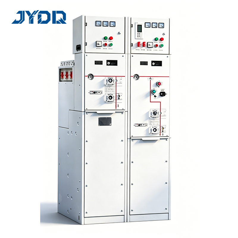
What Is RM6 Gas-Insulated Switchgear?
RM6 Gas-Insulated Switchgear is a medium-voltage ring main unit (RMU) designed for secondary distribution networks operating at 12kV and 24kV. The switchgear houses all live components—busbars, circuit breakers, and disconnectors—within a sealed stainless steel enclosure filled with sulfur hexafluoride (SF6) gas at positive pressure. This sealed-for-life design delivers IP67 ingress protection, eliminating the need for periodic gas refilling or internal maintenance over an expected service life measured in decades.
From a distribution system design perspective, selecting the right switching equipment is a balancing act between grid topology requirements, fault protection specifications, and future network expansion. RM6-type ring main units occupy a well-defined role in this framework: they enable loop-feed distribution configurations that allow utility engineers to maintain supply continuity when a fault occurs on one cable section, isolating the affected segment while restoring power to the rest of the network.
Key Technical Characteristics
Rated voltage range: 12kV to 24kV, covering secondary distribution voltage levels used across European IEC-aligned networks and equivalent systems in Asia, Africa, and the Middle East.
SF6 gas insulation: All live components are sealed within a gas-filled stainless steel tank, providing consistent dielectric performance regardless of ambient humidity, dust, or condensation—a critical advantage in installations where air-insulated equipment would require environmental controls.
IP67 protection rating: The fully sealed enclosure withstands temporary immersion, making RM6 units suitable for underground cable vaults, basement substations, and other confined or flood-prone locations.
Internal arc withstand capability: Designed to contain the effects of an internal arc fault, limiting damage propagation and protecting both personnel and adjacent infrastructure in the event of a fault.
Compact, metal-enclosed construction: The modular design reduces substation footprint compared to conventional air-insulated switchgear, supporting installations in space-constrained urban substations, industrial buildings, and underground distribution nodes.
Customizable configuration: Units can be engineered to accommodate different circuit arrangements, protection relay specifications, and cable entry layouts to match site-specific requirements. For most projects, a standard ring main unit configuration is adequate. The specification changes when applications introduce non-standard protection scheme requirements, unusual cable entry geometry, or extended busbar arrangements—at which point the supplier's customization capability becomes the decisive selection factor.
IEC standards alignment: Products in this category are designed and tested in alignment with relevant IEC switchgear standard categories, including type tests covering dielectric withstand, short-circuit ratings, and arc fault containment. The applicable edition and specific test requirements should be confirmed with the supplier and the relevant certification body for your target market before specifying.
Common Applications
RM6 Gas-Insulated Switchgear is deployed across a broad range of secondary distribution applications where compactness, reliability, and minimal maintenance are primary requirements.
Urban loop-feed distribution networks: Ring main units are the enabling component for N-1 redundancy in medium-voltage distribution. If you are engineering an urban network where supply continuity is non-negotiable—residential districts, commercial zones, or healthcare facilities—a loop-feed topology built around RM6 switchgear provides the fault isolation and switching flexibility that radial distribution cannot match.
Underground cable substations: Confined underground distribution points benefit directly from the IP67 rating and compact footprint. The sealed enclosure removes the maintenance access requirements that conventional switchgear would impose in these environments.
Airport, railway, and transit infrastructure: High-uptime requirements and space constraints in transit infrastructure make gas-insulated switchgear the standard choice for traction substations and station distribution points.
Power generation station auxiliary distribution: On-site auxiliary distribution at power generation facilities—including both conventional and renewable installations—requires reliable medium-voltage switching that can operate across variable environmental conditions.
Industrial facility secondary distribution: Manufacturing plants and industrial parks with significant motor loads benefit from the fault containment and supply continuity features of ring main unit configurations.
Generator changeover applications: In facilities requiring transitions between grid supply and generator change over switch configurations, medium-voltage ring main units can be integrated into the switching architecture to manage source transitions at the distribution level rather than only at the low-voltage tier.
How to Select the Right RM6 Gas-Insulated Switchgear Configuration
Selection of RM6 Gas-Insulated Switchgear involves more than voltage rating and switching capacity. The factors that most consistently determine whether a unit meets project requirements include:
Circuit breaker selection criteria: The choice between a load break switch, a circuit breaker, and a combination unit depends on the protection scheme required at each network node. For nodes where fault clearing is assigned to upstream protection, a load break switch is typically sufficient. Where the unit must provide independent fault clearing capability, a circuit breaker is required—and the circuit breaker selection criteria should include short-circuit current level, operating duty cycle, and protection relay interface compatibility.
Loop configuration requirements: Specify whether the installation requires a two-way ring, a three-way ring, or an extended modular configuration with multiple feeder positions. The number of switching positions and the busbar arrangement drive the physical dimensions and cable routing requirements for the substation room.
Cable entry configuration and cable termination procedure: Installation-phase complications in this area are consistently underestimated at the specification stage. Projects that appear straightforward can encounter delays when the unit arrives on site and the cable entry geometry does not align with the conduit and cable routing established during civil design. Before finalizing the equipment specification, confirm the cable termination procedure requirements—including cable size, termination type, and entry direction—with the supplier, and verify that the civil layout accommodates the required clearances. Substation accessories including cable termination kits and earthing components should be specified and sourced in the same procurement package to avoid interface gaps at commissioning.
IEC compliance versus local grid code requirements: When RM6 Gas-Insulated Switchgear must serve infrastructure projects in markets where the local grid authority's requirements diverge from IEC switchgear standards, the question of which compliance basis governs procurement requires a project-by-project determination with the relevant authority. Both frameworks can be technically valid, but they are not always identical in test scope or documentation format. Confirm this alignment during the pre-specification stage, not after manufacturing has begun.
Installation space and clearance planning: Available installation space is frequently assessed based on equipment footprint dimensions alone, without accounting for cable entry zones, protection relay access panels, and minimum clearance requirements around the enclosure. Equipment that fits in the nominal space plan may not satisfy clearance requirements once accessories and cable terminations are factored in. Verify complete installation requirements—including accessory dimensions—before confirming the substation room layout.
Why RM6 Gas-Insulated Switchgear Matters for Network Reliability
Operational reliability in medium-voltage distribution is a baseline engineering requirement in utility and critical facility applications, not a feature to be balanced against cost. Equipment failure at the ring main unit level can affect an entire distribution loop, triggering outages that cascade to multiple downstream loads. This makes reliability evidence—design validation, type test documentation, factory test records—a primary evaluation input when assessing an unfamiliar supplier.
For procurement teams without in-house high-voltage engineering expertise, the specification process for RM6 Gas-Insulated Switchgear contains technical interfaces—protection relay coordination, cable entry compatibility, grid authority documentation requirements—where misspecification creates project delays and cost overruns. Engaging the supplier's application engineering capability early in the specification process aligns the unit configuration with your specific network topology and protection scheme before the order is placed.
Customization capability is a material differentiator in this product category. Standard RM6 ring main unit configurations cover the majority of distribution applications. The requirements change when projects introduce non-standard protection relay types, unusual cable entry configurations, or specific environmental protection needs—at which point a supplier's ability to engineer to exact specifications becomes the factor that determines whether the equipment meets project requirements without field modifications at commissioning.
Lead time planning is a practical procurement consideration that is frequently underestimated for customized medium-voltage switchgear. Units engineered to non-standard specifications require design confirmation, manufacturing, and factory testing before shipment. Early supplier engagement during the project design phase reduces the risk of schedule impacts caused by late specification changes or unforeseen configuration requirements.

 EN