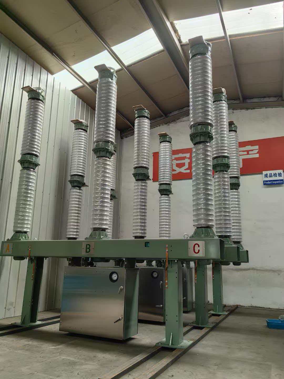
Transmission substations depend on reliable interruption equipment to manage power flow safely and efficiently across regional grids. Sulfur hexafluoride circuit breakers operating at 110kV and 145kV voltage levels have become the standard choice for these critical infrastructure applications because of their superior arc-quenching properties, compact footprint, and long operational life. Understanding how these devices fit into transmission substation design helps utilities plan expansions, replace aging assets, and optimize system reliability.
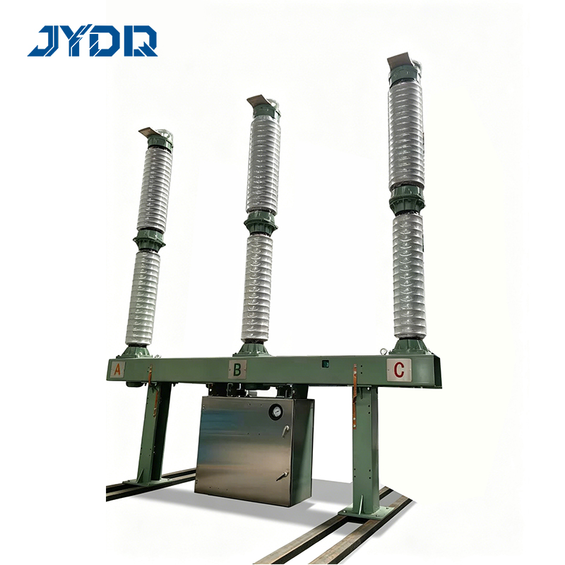
The integration of 110kV and 145kV units into transmission networks requires careful attention to voltage class compatibility, fault ratings, and operational duty cycles. These circuit breaker models deliver exceptional performance in outdoor substation environments, where they handle routine switching operations and respond instantly to fault conditions. Their role spans feeder protection, bus-tie isolation, and main transformer switching, making them indispensable in modern 110kV and 145kV substation architecture.
Voltage Class Requirements and Transmission Design
Understanding 110kV and 145kV Operating Levels
The 110kV voltage class serves as a primary distribution backbone in many regional transmission networks, while the 145kV level represents an intermediate step toward ultra-high-voltage transmission corridors. Both voltage ratings require distinct dielectric strength and mechanical clearance specifications that circuit breaker manufacturers must satisfy. A sulfur hexafluoride circuit breaker designed for 110kV service differs in insulation coordination, contact geometry, and operating mechanism from its 145kV counterpart, yet both leverage SF6 gas technology for superior arc extinguishing performance.
Transmission utilities select between 110kV and 145kV equipment based on regional load forecasts, interconnection agreements, and long-term growth strategies. The 145kV standard offers higher power transfer capacity per circuit, reducing the number of parallel feeders required and lowering overall substation land footprint. Conversely, 110kV substations proliferate where load density remains moderate or where existing infrastructure already operates at this voltage class. Both voltage tiers benefit equally from advanced SF6 interruption technology, which ensures consistent performance regardless of switching duty or fault magnitude.
Coordination with Substation Protection Schemes
Transmission substations employ layered protection strategies where multiple relays and breaker units coordinate to isolate faults while preserving system stability. Circuit breakers at 110kV and 145kV levels must respond to relay signals within strict timing windows, typically between 50 and 200 milliseconds depending on distance relaying sensitivity and load-shedding priorities. The interrupting capacity of these breakers must exceed the maximum three-phase fault current that transmission studies predict for each substation location, ensuring safe arc extinction even under extreme fault conditions. Modern SF6 technology delivers consistent interrupting performance across a wide range of fault currents, supporting both primary and backup protection roles simultaneously.
Arc Interruption Performance and SF6 Technology
How Sulfur Hexafluoride Enables Reliable Breaking
Sulfur hexafluoride gas excels at extinguishing electric arcs because its molecules possess exceptional electron affinity and thermal recovery characteristics. When contacts separate inside an SF6-filled chamber, the expanding arc creates a pressure wave that forces ionized gas away from the contact gap. The SF6 molecules swiftly recombine and cool the arc plasma, reducing the conductivity of the gap volume and forcing the arc to extinguish within a few milliseconds. This rapid quenching mechanism allows 110kV and 145kV circuit breakers to interrupt fault currents that would take much longer to clear in oil-immersed or vacuum designs, reducing mechanical stress on connected equipment and minimizing system voltage dips.
Transmission operators depend on this speed and reliability to protect costly transformer windings, transmission line insulators, and sensitive control electronics. SF6 interruption also produces negligible contact erosion compared to air or oil technologies, enabling these breakers to sustain thousands of switching operations without scheduled contact replacement. A properly maintained SF6 circuit breaker can operate for 30 years or more in a transmission substation, providing excellent return on capital investment while reducing lifecycle maintenance costs and emergency downtime exposure.
Insulation Coordination and Overvoltage Protection
Transmission networks experience transient overvoltages caused by lightning strikes, switching operations, and fault clearing sequences. Equipment at 110kV and 145kV voltage classes must withstand standard switching impulse and lightning impulse stress levels defined by international standards. SF6-filled circuit breakers offer superior dielectric strength compared to air or vacuum, allowing manufacturers to design more compact breaker frames while maintaining the same safety margins. The gas's dielectric withstand also allows for tighter phase-to-ground and phase-to-phase spacing, reducing physical footprint—a critical advantage when retrofitting transmission substations with space constraints or when expanding existing facilities onto limited real estate.
Installation, Maintenance, and Operational Considerations
Outdoor Substation Integration and Environmental Factors
Most transmission substations employ outdoor configurations where 110kV and 145kV breakers face rain, snow, humidity, salt spray, and temperature extremes. Modern SF6 circuit breakers incorporate robust enclosures, sealed contact chambers, and stainless-steel hardware that resist corrosion and maintain gas integrity over decades. Installation requires qualified technicians to verify phase rotation, grounding continuity, and control wiring before energizing the breaker. Proper foundation design prevents settlement that could misalign breaker linkages and cause premature contact wear. Environmental monitoring and periodic inspections confirm that seals remain intact and SF6 gas purity stays within manufacturer tolerance, typically checked every 5 to 10 years using moisture content analysis.
Transmission utilities schedule preventive maintenance during spring or fall outage windows to inspect contact surfaces, replace mechanical seals if needed, and recondition SF6 gas through degassing and drying processes. Condition-based monitoring using thermal imaging and partial discharge diagnostics extends maintenance intervals and predicts failures before they occur. These proactive approaches minimize the risk of unexpected breaker failure during peak load periods and reduce cumulative outage costs across the substation fleet.
Spare Parts Strategy and Supply Chain Planning
Transmission operators maintain strategic spare stocks of critical 110kV and 145kV breaker components—including contact assemblies, operating mechanisms, and auxiliary relay modules—to minimize response time if a failure occurs. Lead times for complete breaker units typically range from 12 to 24 weeks, making it impractical to order equipment only after a failure is discovered. Utilities align their spare parts procurement with equipment lifecycle analysis, replacing breakers approaching their design life before failure risk becomes significant. Coordination with equipment manufacturers helps utilities forecast parts availability, plan major overhauls, and balance budget allocations across multiple substation locations.
FAQ
What fault current ratings should a 145kV breaker possess for transmission use?
Transmission-class 145kV circuit breakers typically carry interrupting capacity ratings between 25 and 50 kiloamperes, depending on the specific substation fault level and interconnection strength. Utilities conduct short-circuit studies for each substation location to determine the maximum symmetrical fault current and select breaker ratings that exceed this value by a safety margin. Higher fault levels in strong transmission corridors demand 145kV breakers rated toward the upper end of this range, while weaker radial networks may accept lower ratings if the connected generation and source impedance limit fault current naturally.
How does SF6 gas degradation affect 110kV circuit breaker performance?
Contamination of SF6 gas by moisture, oxygen, or decomposition by-products gradually reduces the dielectric strength and arc-quenching ability inside the breaker chamber. High-voltage stress accelerates decomposition, especially if moisture is present, creating insulating faults and reducing interrupting reliability. Modern breakers include gas density monitoring devices that alarm when pressure falls below minimum operating levels, prompting technicians to investigate and restore gas purity before safety is compromised. Regular gas sampling and laboratory analysis of moisture and particulate content help utilities detect degradation early and plan timely maintenance or gas reclamation procedures.
Can existing 110kV substations be upgraded to 145kV operation?
Upgrading a substation from 110kV to 145kV typically requires replacement of major equipment—transformers, 110kV breakers, insulators, and control systems—making it a significant capital project rather than a simple retrofit. The physical structure, foundation design, and control building capacity may also require modifications to accommodate higher voltage clearances and new control schemes. Most utilities find it more economical to build new 145kV substations where load growth justifies expansion, while maintaining and extending the life of existing 110kV facilities in areas where demand remains stable or grows slowly.

 EN