Selecting and integrating a dry type transformer with your electrical infrastructure requires careful attention to switchgear compatibility, voltage ratings, and operational demands. The dry type transformer has become the preferred choice in industrial and commercial applications because it eliminates the need for cooling oil, reducing fire risk and maintenance complexity. However, successful integration depends on precise alignment between the transformer specifications and the switchgear components that manage, protect, and distribute power throughout your system. This article explores the critical steps and considerations necessary to ensure your dry type transformer works seamlessly with both high-voltage and low-voltage switchgear configurations.
Proper switchgear integration represents one of the most critical phases of system design. When you plan a power distribution setup, the transformer and switchgear must operate as a coordinated unit, not as isolated components. The voltage ratings, current capacities, protective relay settings, and physical dimensions all must align to create a reliable, efficient electrical infrastructure. Understanding these alignment principles protects your investment and ensures your system meets both current operational needs and future expansion requirements.
Understanding Voltage Rating Compatibility
Selecting Primary and Secondary Voltage Levels
The first step in matching your dry type transformer with switchgear involves confirming voltage compatibility across all system stages. Your incoming utility supply voltage, the primary winding rating of the transformer, and the secondary voltage available to the low-voltage switchgear must all correspond correctly. If your facility receives 13.8 kV from the utility, your primary switchgear must handle that voltage, and your transformer primary coil must be rated for it. Similarly, if you need 480 volts for your main distribution panel, the transformer secondary must deliver exactly that voltage, and your low-voltage switchgear must be designed for 480-volt operation. Mismatches in voltage specifications can damage equipment, create safety hazards, and violate electrical codes.
Voltage Drop Considerations in System Design
Beyond nominal ratings, you must account for voltage drop across conductors, connections, and the transformer impedance itself during power distribution. A dry type transformer typically exhibits an impedance percentage that causes a measurable voltage reduction under load. When the transformer secondary feeds a low-voltage switchgear, the cables connecting them introduce additional resistance. The combined voltage drop must remain within acceptable limits, typically 3 percent on primary circuits and 5 percent on secondary circuits according to most electrical standards. Proper system design calculates these drops and confirms that critical loads receive sufficient voltage even during peak demand periods. This attention to voltage drop during switchgear integration ensures motor performance, lighting consistency, and protection system reliability.
Matching Current and Short-Circuit Capacity
Aligning Transformer and Switchgear Ratings
Current capacity represents the second major alignment requirement when integrating a dry type transformer with switchgear components. The transformer's full-load current capacity must not exceed the rating of the primary switchgear, incoming line components, or the secondary switchgear downstream. A transformer rated at 750 kilovolt-amperes with a 13.8-kilovolt primary winding will draw approximately 31.4 amperes on the primary side. Your high-voltage switchgear must accommodate this continuous current safely. On the secondary side at 480 volts, that same transformer produces approximately 902 amperes. Your low-voltage switchgear must be rated to handle this amperage continuously without exceeding thermal limits. Undersizing switchgear creates overheating risks and potential failures during normal operation.
Short-Circuit Current Coordination
Beyond steady-state current, switchgear integration requires coordination of short-circuit capacity and protective device settings. When a fault occurs downstream of the transformer, the transformer contributes fault current that must be interrupted by protective devices upstream and distributed correctly by downstream switchgear. The high-voltage switchgear must withstand and interrupt the maximum fault current available from your utility and the transformer. The low-voltage switchgear must have sufficient short-circuit rating to safely handle the fault current the transformer can supply. Protective devices such as fuses, circuit breakers, and relays must be coordinated so that the device nearest a fault operates first, minimizing damage and service interruption. This coordination ensures your power distribution system remains stable during abnormal conditions and that fault currents do not damage switchgear components.
Physical Installation and Switchgear Integration Logistics
Spatial Planning and Electrical Distance Requirements
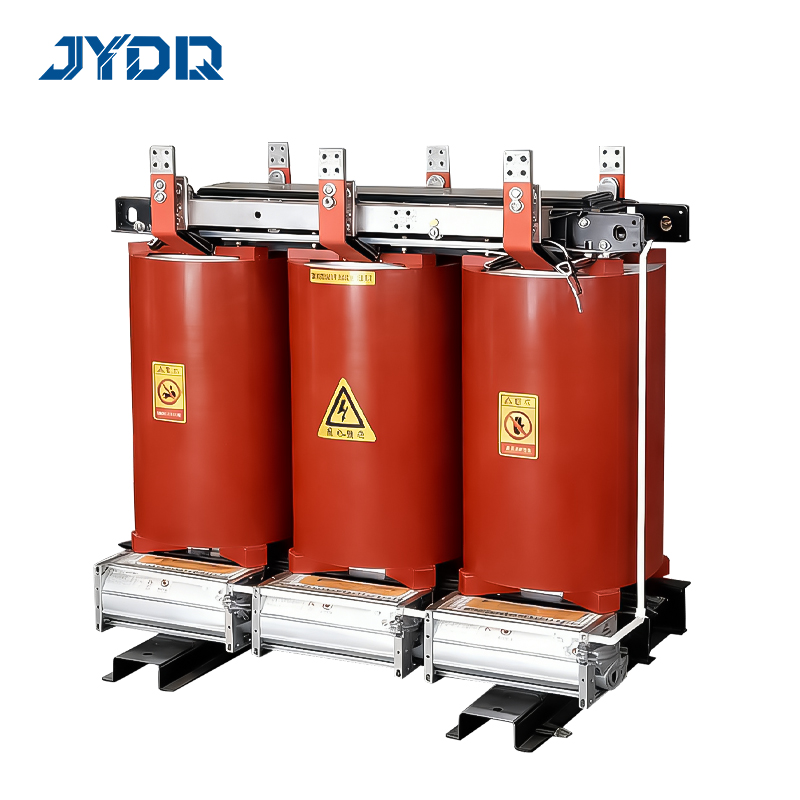
Physical placement of the dry type transformer relative to high-voltage and low-voltage switchgear affects system efficiency and installation complexity. The transformer should be positioned to minimize the length of primary cables connecting to the high-voltage switchgear, reducing voltage drop and installation costs. Equally important, the secondary cables connecting the transformer to the low-voltage switchgear should be as short as practical to limit secondary voltage drop and reduce electromagnetic interference. In many facilities, locating the transformer in a central position relative to its loads optimizes power distribution and reduces conductor cross-sections required. Adequate clearance around the transformer is essential for cooling, maintenance access, and safety compliance. Ventilation requirements for dry type transformers differ from oil-immersed designs because air circulation cools the resin-cast windings, so physical proximity to low-voltage switchgear must not restrict airflow.
Cable Selection and Switchgear Termination
The cables connecting the dry type transformer to both primary and secondary switchgear must be sized correctly and terminated securely. Primary cables carrying high-voltage current from utility supply through high-voltage switchgear to the transformer primary must be rated for the maximum fault current and the continuous current mentioned earlier. Secondary cables from the transformer secondary to the low-voltage switchgear must similarly be sized to handle full-load current without exceeding acceptable temperature rise. Cable terminations at switchgear require careful attention to mechanical security, phase sequence, and grounding continuity. Loose connections generate heat, increase resistance, and can trigger nuisance faults. Proper termination following manufacturer specifications and electrical code requirements ensures reliable power distribution and reduces the likelihood of failures during operation or switchgear integration commissioning.
Protective Device Coordination and Control Integration
Relay Settings and Switchgear Protection Strategies
Integrating protective relays with both high-voltage and low-voltage switchgear requires coordination planning to prevent unnecessary outages while protecting equipment. On the primary side, overcurrent relays in the high-voltage switchgear must be set to detect external faults without responding to transformer inrush current that occurs at startup or after a reclosure. Transformer inrush current can be five to ten times the full-load current and lasts for a fraction of a second, so relay timing must be coordinated with transformer characteristics. On the secondary side, low-voltage protective devices must respond quickly to short circuits and overloads but must allow for safe equipment operation during normal transients. Selective coordination ensures that only the protection device nearest a fault operates, preserving service to unaffected portions of your power distribution system.
Control Systems and Monitoring for Switchgear Integration
Modern power distribution increasingly incorporates monitoring and control systems integrated with switchgear to provide real-time visibility into transformer and system performance. Temperature sensors on the dry type transformer can trigger alarms or control ventilation fans to optimize cooling and prevent overheating. Power meters and demand recorders at the switchgear help operators manage load distribution and identify potential issues before they cause failures. Some installations include supervisory control and data acquisition systems that enable remote monitoring of switchgear position, transformer temperature, and system voltages. This integration improves operational visibility and enables preventive maintenance scheduling based on actual equipment condition rather than fixed time intervals.
FAQ
What voltage ratings must a dry type transformer have to match with high-voltage switchgear?
The transformer primary winding voltage rating must exactly match the utility supply voltage or the incoming voltage from high-voltage switchgear. Common primary voltages include 4.16 kV, 6.6 kV, 10 kV, 13.8 kV, and 34.5 kV depending on your facility's electrical service. The dry type transformer specifications must also include the correct kilovolt-ampere capacity and impedance percentage to ensure compatibility with switchgear protection and system design requirements.
How do I ensure short-circuit current from the dry type transformer is properly managed by low-voltage switchgear?
Calculate the secondary short-circuit current available from the transformer using the transformer impedance percentage, kilovolt-ampere rating, and primary fault current level. Confirm that your low-voltage switchgear has an interrupt rating equal to or greater than this calculated value. Work with the switchgear manufacturer to select protective devices rated for the available fault current and to coordinate relay settings and circuit breaker characteristics throughout your power distribution system.
Can I install a dry type transformer close to low-voltage switchgear without affecting cooling performance?
Yes, but careful planning is essential to maintain adequate ventilation and airflow around the transformer. Ensure that switchgear does not block air inlet or outlet openings on the dry type transformer and that the surrounding area allows heat dissipation. Some installations use thermostatic fan controls to enhance cooling when needed, and proper spacing between equipment maintains thermal performance throughout normal operating conditions and preserves system design efficiency.

 EN