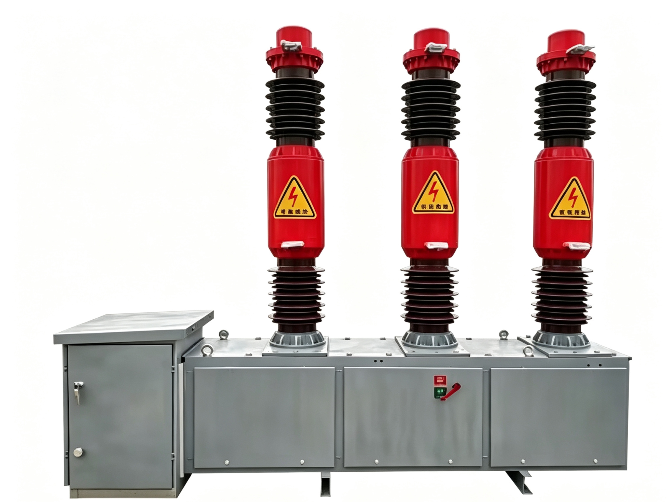
Effective protection coordination is vital for any oil immersed transformer installation. An oil immersed transformer represents a significant capital investment and critical infrastructure component within industrial facilities and utility networks. Without proper transformer protection systems working in concert, equipment damage, unexpected outages, and safety hazards can escalate rapidly.
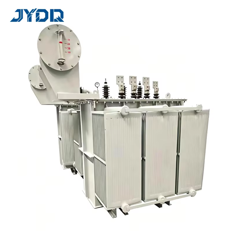
Protection coordination for an oil immersed transformer ensures that multiple protective devices operate in the correct sequence when faults occur. The goal is to isolate only the faulted equipment while maintaining service to unaffected portions of the network. This requires careful planning, precise relay calibration, and strategic circuit breaker placement throughout the power system.
Understanding Transformer Protection Fundamentals
Core Protection Elements
Transformer protection involves several key components working together. The primary layer includes overcurrent protection through relay devices and circuit breaker coordination. These systems detect excessive current flow caused by internal faults, external short circuits, or overload conditions. A properly designed transformer protection scheme monitors both primary and secondary sides of the equipment.
Internal faults within an oil immersed transformer can cause rapid temperature rise and pressure buildup. Gas accumulation detection, winding temperature monitoring, and oil level sensing provide critical early warnings. Combined with external protection, these layers create a comprehensive defense against catastrophic failure and operational interruption.
Protection Coordination Objectives
The main objective of transformer protection coordination is selectivity, meaning the closest protective device to the fault clears it first. Without proper coordination, unnecessary outages occur upstream, affecting larger portions of the system. This principle drives all relay and circuit breaker settings throughout the protection scheme.
Relay Configuration and Settings
Overcurrent Relay Coordination
Overcurrent relay devices form the backbone of transformer protection strategies. For an oil immersed transformer, both instantaneous and time-delay overcurrent functions must be configured. Time-delay settings allow temporary overcurrent conditions to pass through without tripping, while instantaneous settings catch severe faults immediately.
The coordination process requires calculating fault levels at different points in the system. These calculations determine appropriate relay pickup settings and time delay intervals. A relay protecting an oil immersed transformer must be set sensitive enough to detect all relevant faults, yet insensitive enough to allow downstream protective devices to operate first during external faults.
Differential Relay Protection
Differential relay devices provide the most specific protection for transformer internal faults. These relays compare current entering and leaving the transformer windings. Any mismatch indicates an internal fault, triggering immediate trip action. Differential protection is fast and selective because it responds only to transformer faults, not external system disturbances.
Configuring differential relay for an oil immersed transformer requires careful current transformer selection and burden calculation. The relay must distinguish between inrush current during energization and genuine fault conditions. Modern numerical relays include harmonic restraint and inrush detection algorithms that improve reliability and security.
Circuit Breaker Coordination Strategy
Primary and Secondary Breaker Integration
Circuit breaker devices at both primary and secondary positions must coordinate with relay settings to achieve selective protection. The primary circuit breaker, typically on the utility or source side, should be slower to operate than secondary breakers during downstream faults. This time-current characteristic coordination allows lower-level protective devices to clear faults first.
For an oil immersed transformer protection scheme, coordination margins must be maintained between successive breaker levels. A typical margin ranges from 0.3 to 0.5 seconds to ensure clear differentiation between operating times. This separation prevents unwanted cascading outages and maintains system stability during transient conditions.
Fault Current Withstand Capability
Each circuit breaker component must be rated for the maximum fault current it could experience. An oil immersed transformer installation requires careful fault current analysis to select appropriately rated devices. Undersized breakers may fail to interrupt high currents, while oversized selections add unnecessary cost and slow response time.
The transformer protection coordination plan must account for evolving system conditions. As network configurations change or nearby generation capacity increases, fault levels may rise above original design assumptions. Periodic review and recalculation of protection settings ensures continued equipment safety and system reliability.
FAQ
What are the main types of faults that transformer protection must detect?
An oil immersed transformer faces both internal and external fault conditions. Internal faults include phase-to-phase short circuits, winding-to-ground faults, and turn-to-turn shorts within the coils. External faults occur on the connected power system beyond the transformer terminals. A complete transformer protection scheme must respond appropriately to all fault categories while avoiding unnecessary trips from transient phenomena.
How do relay settings differ between primary and secondary transformer circuits?
Relay configuration depends on the specific position within the power system hierarchy. A relay protecting transformer primary windings typically includes lower current thresholds than secondary-side relays because primary circuits carry lower current for the same power level. Additionally, primary relays must coordinate with utility equipment, while secondary relays focus on industrial load protection. Each relay requires customized settings based on local fault levels, transformer impedance, and protection objectives.
Why is timing coordination between protective devices critical?
Proper timing coordination ensures that only the protective device nearest the fault operates. If upstream devices trip simultaneously, unnecessary outages affect uninvolved circuits. Time-current coordination curves define operating characteristics for each relay and circuit breaker across the expected fault current range. This coordination principle minimizes service interruptions and maintains system resilience during emergency conditions.

 EN