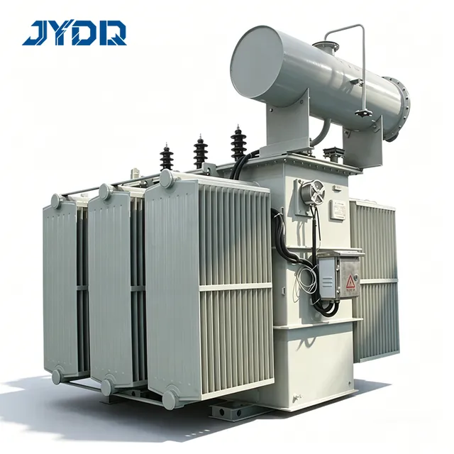
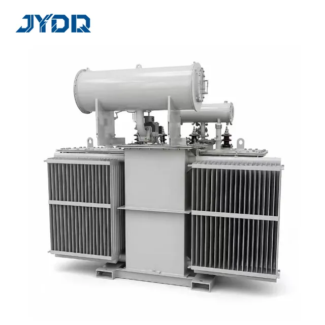
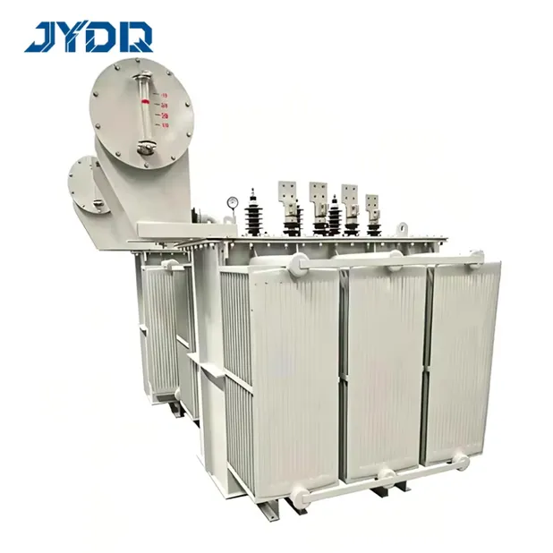
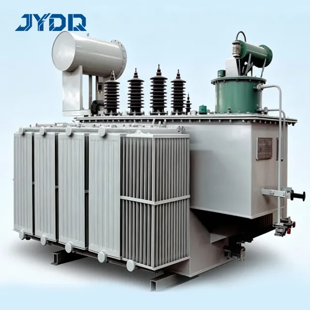
35kV Submersible Transformer: Product Overview
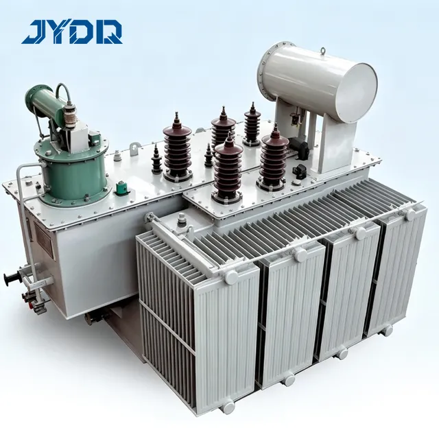
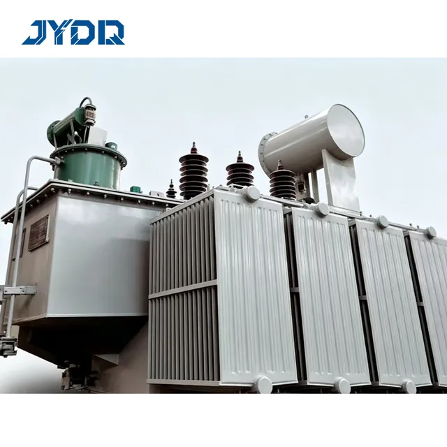
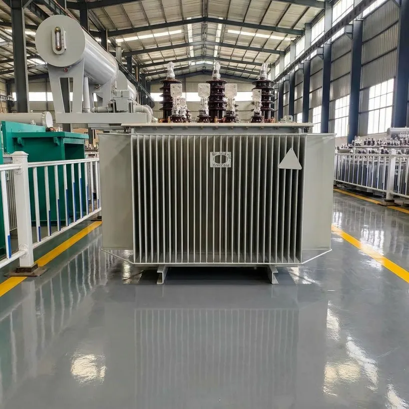
The 35kV Submersible Transformer is presented as an S11/SZ11 three-phase oil-immersed power transformer for 35kV primary-voltage distribution, utility substations, industrial grid connections, and renewable-energy projects. Available capacity information in the source material covers 800kVA to 31,500kVA. Each 35kV Submersible Transformer should be specified against the actual voltage ratio, frequency, load profile, connection method, and installation environment rather than selected from capacity alone.
Source information describes copper windings, a CRGO silicon-steel core, and a hermetically sealed corrugated tank. The 35kV Submersible Transformer can be configured for 50Hz or 60Hz systems, with listed vector-group options including Dyn11, YNd11, and YNyn0. Final values and accessories require engineering confirmation for the project specification.
Selection Framework
For a 35kV Submersible Transformer, the important choice is not simply oil-immersed versus another construction. Buyers should review the local grid voltage, permitted tap range, expected loading, impedance requirement, neutral arrangement, cooling duty, and documentation required for energization. A catalogue rating can look suitable while the installed system conditions require a different tap arrangement or protection interface.
The source material distinguishes S11 units with off-circuit tap adjustment from SZ11 units with on-load tap changing. Where grid voltage is stable and adjustments can be planned during a de-energized maintenance window, an off-circuit arrangement may suit the project. Where voltage changes under load must be managed, an on-load option can be assessed. This is conditional guidance: the selected tap range and control scheme must match the grid study and the purchaser requirements.
Low no-load loss alone does not determine operating cost. The load pattern, operating hours, winding losses, cooling conditions, and allowable temperature rise all affect the complete assessment. Ask for the guaranteed loss schedule and test scope for the exact rated capacity instead of comparing generic claims.
Core Specifications from the Existing Product Material
| Parameter |
Listed information |
| High voltage |
35kV; listed alternatives include 33kV, 36kV, 38.5kV, and 40.5kV |
| Low voltage |
10.5kV, 11kV, 6.3kV, 6.6kV, 3.3kV, or 0.4kV, customizable |
| Capacity |
800kVA to 31,500kVA |
| Cooling |
ONAN; ONAF listed for capacities at or above 8,000kVA |
| Standards |
IEC 60076, GB 1094, and GB/T 6451 are listed in the existing material |
| Materials |
100% pure electrolytic copper windings and CRGO silicon steel are stated in the existing material |
These entries describe the existing product information and are not a substitute for an approved drawing, nameplate schedule, or factory test plan. The 35kV Submersible Transformer quotation should identify which values are guaranteed for the selected design.
Functional Features
Winding and core design
The provided description identifies copper windings and a CRGO core. For a 35kV Submersible Transformer, these construction choices are evaluated together with the selected loss level, insulation design, and thermal duty. Request the applicable routine-test and type-test documentation when it is required by the tender.
Hermetic tank concept
The existing content describes a corrugated hermetically sealed tank intended to reduce moisture ingress. Site conditions still matter: installation location, transport, oil handling, coating requirements, containment measures, and maintenance access should be reviewed before release for manufacture.
Configuration flexibility
Voltage ratio, vector group, impedance, cooling configuration, and environmental provisions are identified as customizable. A 35kV Submersible Transformer for a coastal, high-altitude, hot-climate, or variable-grid site should be evaluated with those conditions documented in the RFQ.
Documentation support
IEC compliance is described in the source material. Confirm the applicable edition, local-grid-code requirements, test clauses, certificates, and acceptance documentation with the supplier and project authority before relying on any compliance statement.
Applications and Project Fit
Utility and distribution substations
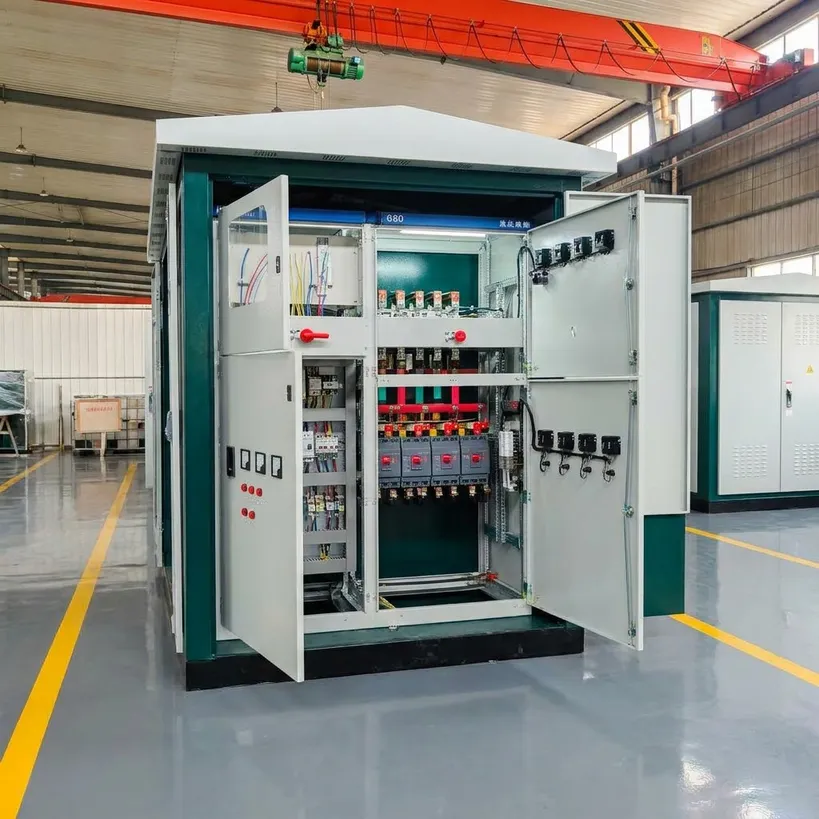
The 35kV Submersible Transformer can be considered for distribution-network projects where the selected voltage ratio and protection coordination align with the utility design. Engineering teams should verify feeder conditions, fault levels, grounding, and the required interface documentation.
Industrial power supply
Large industrial facilities may need a 35kV Submersible Transformer to connect a medium-voltage supply to plant distribution. For continuous processes, review actual load duty, harmonic conditions, ambient temperature, outage planning, and maintenance access before finalizing capacity and cooling.
Renewable-energy grid connection
Wind and solar projects can require project-specific voltage and tap arrangements. When generation output or grid voltage varies, selection should reflect the interconnection study rather than a standard configuration. The final transformer arrangement must be confirmed by the responsible electrical engineer.
RFQ Checklist and Supply Discussion
To obtain a technically comparable proposal for a 35kV Submersible Transformer, provide rated power, HV/LV voltages, frequency, vector group, impedance, tap changer preference, cooling requirement, insulation level, installation altitude, ambient conditions, applicable standards, and required test documents. Clarifying these items early reduces quotation revisions caused by differences in standard inclusions.
The source material lists MOQ of one set, T/T payment, and a 25–45 working day lead-time indication after deposit confirmation, plus export-oriented shipping and packaging references. Commercial terms, production schedule, packing, transport method, and warranty terms should be reconfirmed in the final contract because they depend on the confirmed configuration and destination.
Contact Zhejiang Jingyu Technology Co., Ltd. with the project data sheet for engineering review. The most useful next step is a specification discussion that turns the listed product range into a defined 35kV Submersible Transformer configuration with agreed technical documents and acceptance criteria.
Installation and Acceptance Considerations
Before delivery, confirm the approved outline drawing, terminal arrangement, lifting points, oil containment concept, cable-entry clearances, and access for inspection. The transformer rating must be coordinated with upstream and downstream protective devices, including the required impedance and grounding arrangement. At factory acceptance, the purchaser can define the routine-test records, nameplate data, accessory schedule, packing requirements, and document language needed for the project file. On site, energization should follow the owner’s approved commissioning procedure and local safety rules. These checks do not add product specifications; they help the project team verify that the selected configuration, documentation, transport plan, and installation conditions remain aligned from quotation through handover.
Confirm all final acceptance requirements before energization and handover.

 EN