jdzx9-35-35kv-single-phase-cast-resin-voltage-transformer-with-residual-voltage-winding, jdzx9-35-35kv-single-phase-cast-resin-voltage-transformer-with-residual-voltage-winding, /voltage-transformer-series-10-35-kv
EN
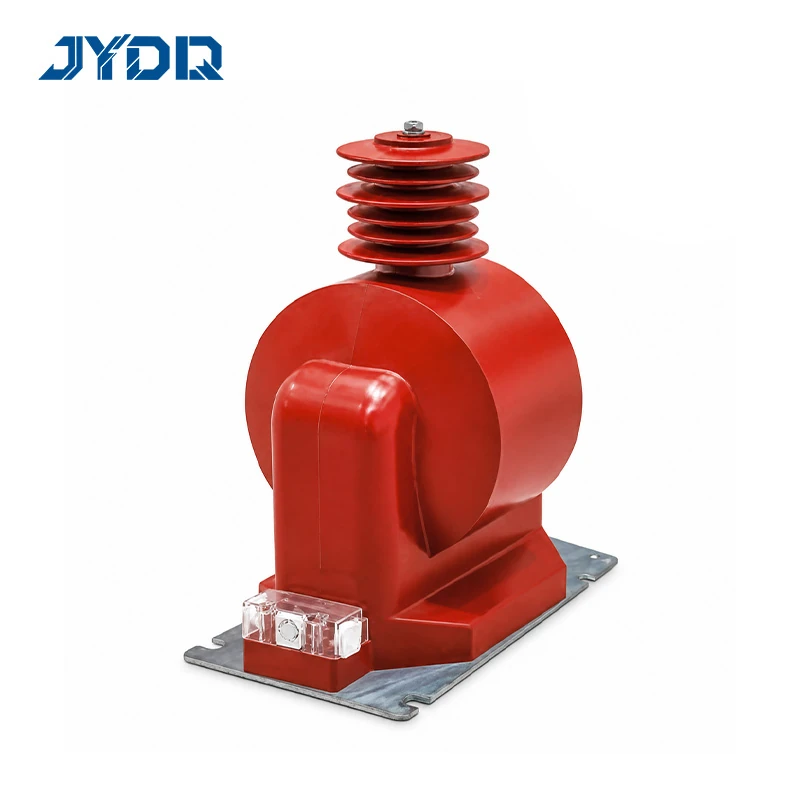
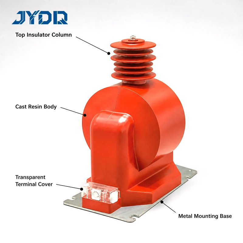
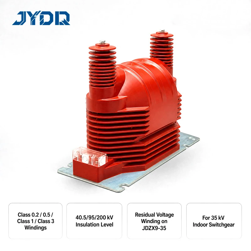
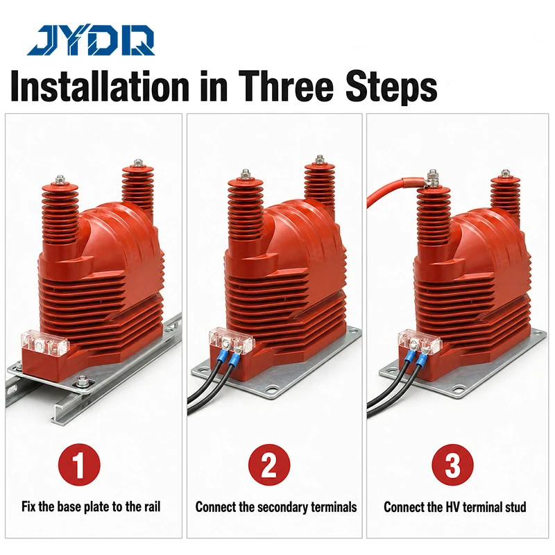
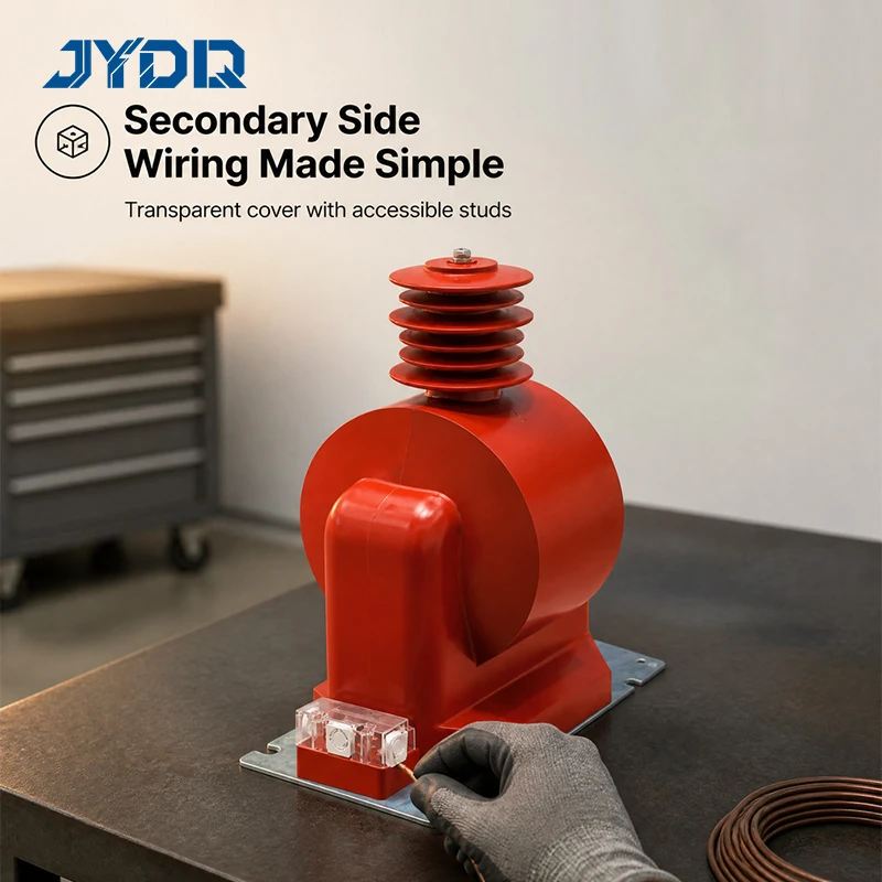
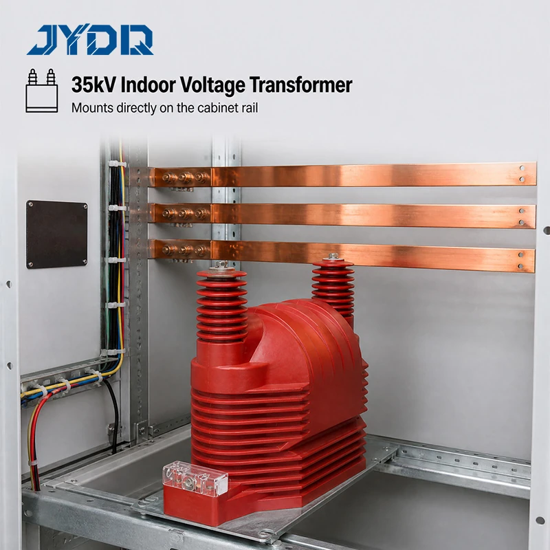
35kV; JDZ9-35Q / JDZX9-35G; Ratios 35000/100 & 35000/√3 /100/√3 /100/3; Classes 0.2-3, 6P(3P); Output 30-800VA; 40.5/95/200kV
This JDZX9-35 entry is a single-phase voltage transformer arrangement for 35 kV circuits. Its documented purpose is voltage measurement where a residual-voltage winding is also required. The selection decision should follow the project circuit: primary-to-secondary ratio, number of windings, required accuracy, connected burden, relay duty, and installation interface all need confirmation before ordering.
It is useful to separate a family label from a project-ready specification. Similar 35 kV instrument transformers can have different secondary circuits and mechanical interfaces. The supplied catalogue data offers a defined basis for comparison, but the approved schematic, wiring figure, and installation drawing remain essential for final application review.
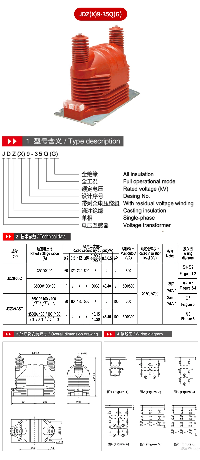
In the code, J denotes voltage transformer, D denotes single phase, Z denotes cast insulation, X identifies the residual-voltage winding, 9 is the design number, and 35 refers to the rated kilovolt level. The materials cover JDZX9-35, JDZ9-35Q, and JDZX9-35G. They are related groups, not automatically interchangeable alternatives.
JDZX9-35 includes the residual-voltage winding. JDZ9-35Q is listed without this winding, and its 6P column is therefore not applicable. JDZX9-35G combines residual-voltage function with an all-insulation construction. Where a medium voltage panel needs residual-voltage information, verify the selected group and its stated secondary configuration rather than relying on a similar name.
The series is stated at 35 kV with an insulation level of 40.5/95/200 kV. Catalogue accuracy entries include 0.2, 0.5, class 1, class 3, combined classes, and 6P(3P) when applicable. Depending on the ratio and row, listed maximum outputs run from 300/300 VA to 800 VA. Those figures are tied to their respective configurations and should not be generalized across the family.
| Selection item | Available catalogue detail |
|---|---|
| System class | 35 kV |
| Phase / insulation | Single phase / cast insulation |
| Insulation level | 40.5/95/200 kV |
| Accuracy options shown | 0.2, 0.5, class 1, class 3, combined entries, 6P(3P) as applicable |
| Maximum-output range | 300/300 VA to 800 VA according to configuration |
| Commercial terms | MOQ 1; T/T; delivery within 20 days after receipt of payment |
For the listed three-winding ratio 35000/√3 / 100/√3 / 100/3, the table shows 30 VA at class 0.2, 90 VA at class 0.5, 180 VA at class 1, 500 VA at class 3, 100 VA at 6P(3P), and 600 VA maximum output. Figure 1 is referenced for the wiring.
The listed four-winding arrangement is 35000/√3 / 100/√3 / 100/√3 / 100/3. Its entries include 15/15 VA, 15/20 VA, 45/45 VA, 100 VA at 6P(3P), and 300/300 VA maximum output, with Figure 2 as the wiring reference. The two arrangements serve different secondary-layout needs, so an RFQ should identify the required circuit clearly.
JDZ9-35Q is catalogued at 35000/100 and 35000/100/100. The single-secondary option shows 60 VA, 120 VA, 240 VA, and 600 VA at classes 0.2, 0.5, 1, and 3, with 800 VA maximum output. Its lack of a residual-voltage winding is an important functional distinction. Choosing a row only because it shows a desirable burden value can create a mismatch if the required residual-voltage circuit is absent.
Technical selection therefore begins with the duty. Confirm whether the application needs standard voltage measurement only or measurement with residual-voltage detection. Then check the required ratio, winding count, accuracy, burden, protection output, and associated transformer connection diagram. This sequence is more reliable than applying one familiar rating to every 35 kV circuit.
A higher nominal rating does not by itself prove a better solution. System compatibility is the key consideration: the device, connected equipment, secondary wiring, and protection logic must work together. The documents support a cast-insulation designation and the stated insulation level, but do not substantiate unlisted certifications, environmental ratings, or tests. If the project has further requirements for transformer insulation material, obtain applicable confirmation before procurement.
The JDZX9-35 mechanical drawing identifies 488±3 mm overall height, one M10 primary terminal at the top, an M8 earth bolt at the base, and four Ø14 mounting holes. The shown base measures 371 mm overall length and 240 mm overall width, with 315±0.7 mm mounting-hole centres and a 200±0.3 mm inner dimension. Compare these figures with the actual mounting support and available clearance.
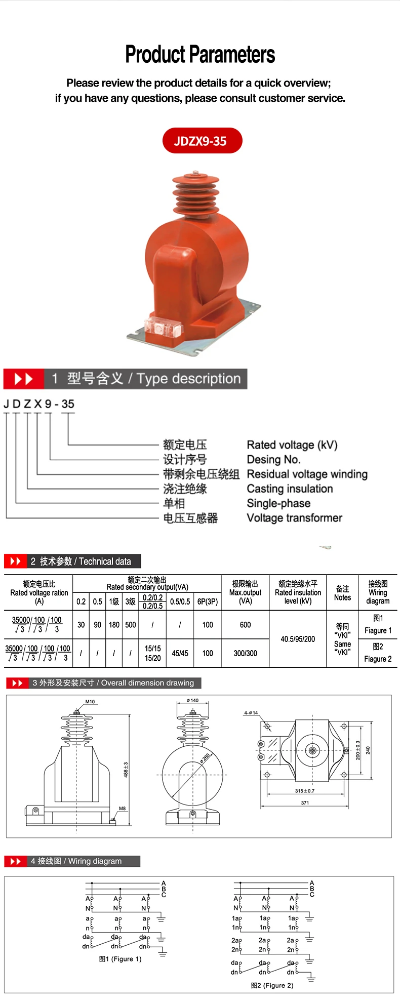
The separate JDZ9-35Q and JDZX9-35G drawing shows 493±3 mm height, two M10 primary terminals spaced 390±1 mm apart, a 420±1 mm by 220±1 mm plan envelope, and four Ø14 holes. Electrical similarities do not guarantee identical mounting. Check the relevant drawing before a retrofit or new installation.
The JDZX9-35 35kV Single-Phase Cast-Resin Voltage Transformer with Residual Voltage Winding may be considered for 35 kV, single-phase circuits requiring voltage measurement and a residual-voltage function, provided the selected ratio and outputs are confirmed. The supplied descriptions point to switchgear-related measurement, earth-fault or residual-voltage detection, accuracy-class metering, and protection arrangements using the listed 6P(3P) output.
For an accurate quotation, state the model group, ratio, winding quantity, accuracy class, secondary burden, required output, wiring requirement, and installation dimensions. That information enables a meaningful distinction between JDZX9-35, JDZ9-35Q, and JDZX9-35G. It also gives the supplier the details needed to compare the requested circuit with the documented series data.
Use the system function as the starting point, validate the exact electrical row next, and confirm physical fit before release. This disciplined approach keeps the inquiry traceable to the available catalogue facts and avoids assuming that one configuration represents every version of the series.
35kV; JDZ9-35Q / JDZX9-35G; Ratios 35000/100 & 35000/√3 /100/√3 /100/3; Classes 0.2-3, 6P(3P); Output 30-800VA; 40.5/95/200kV

 EN