jszjk-3610q-3kv-6kv-10kv-three-phase-cast-resin-voltage-transformer-anti-ferroresonance, jszjk-3610q-3kv-6kv-10kv-three-phase-cast-resin-voltage-transformer-anti-ferroresonance, /voltage-transformer-series-10-35-kv
EN
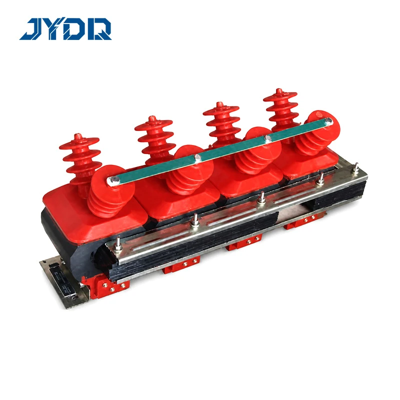
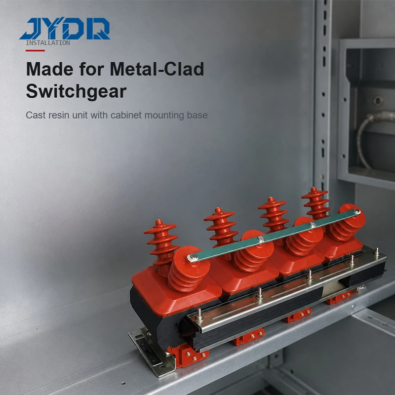
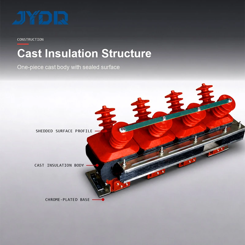
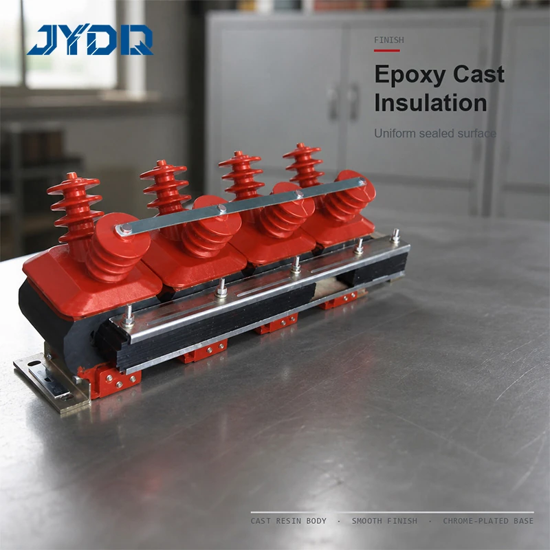
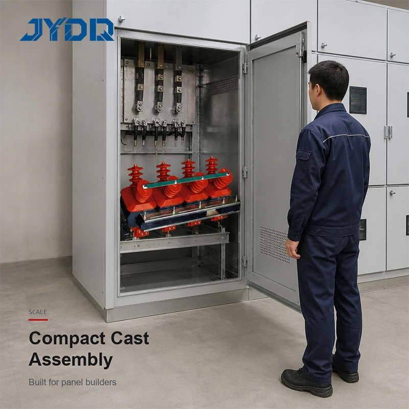
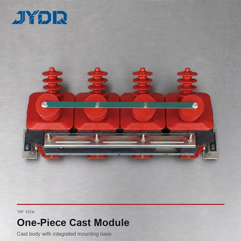
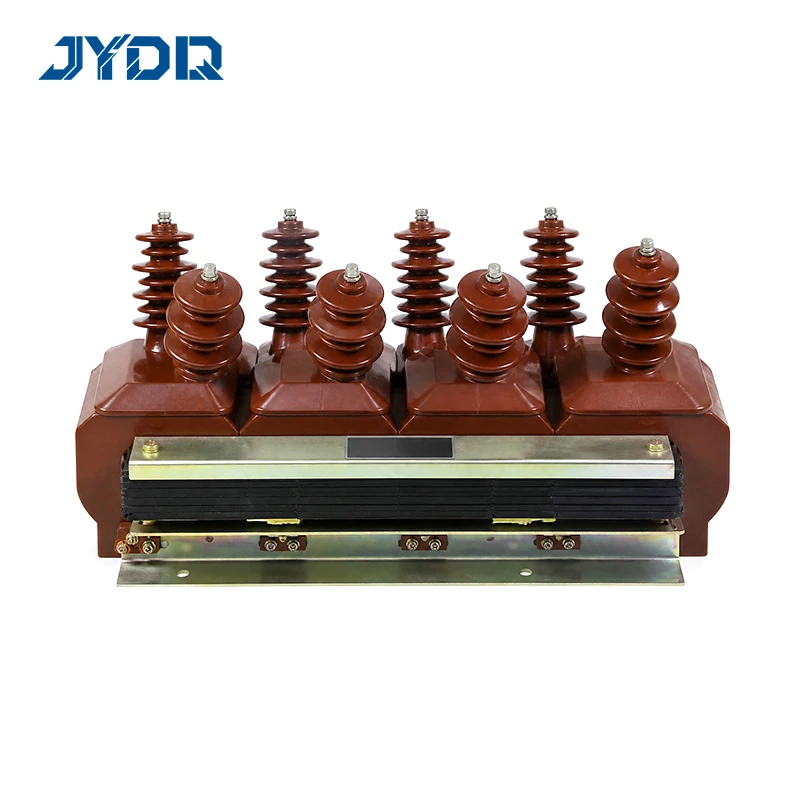
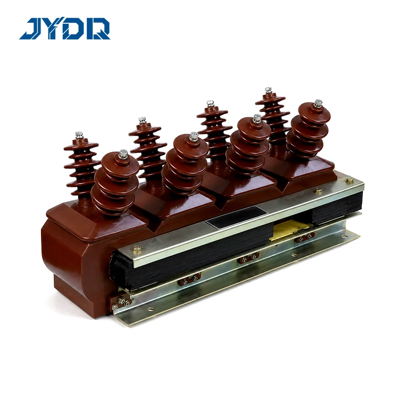
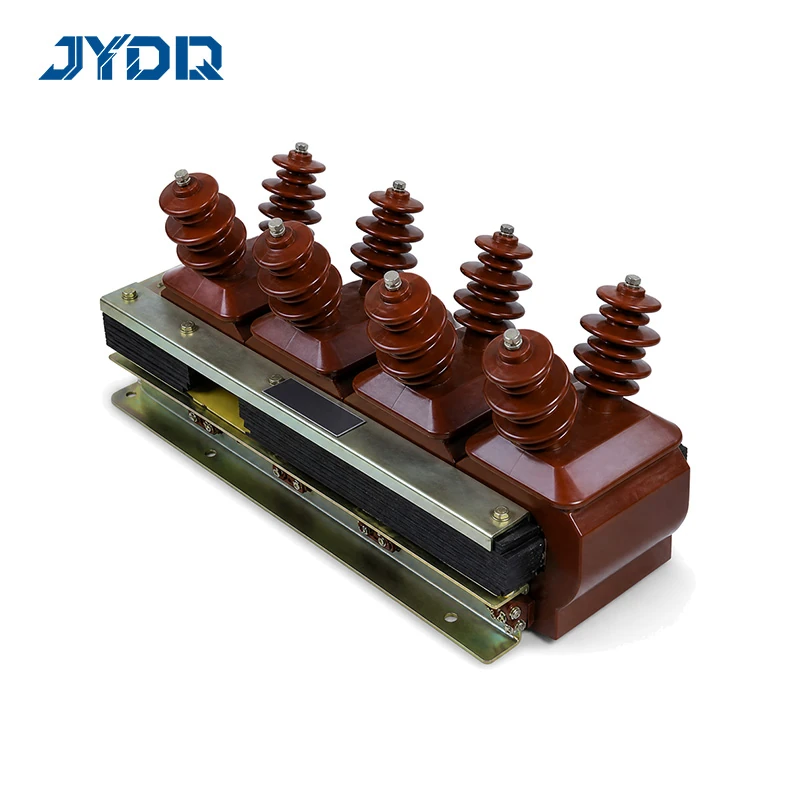
3kV 6kV 10kV Three-Phase; Residual Winding; Full Operational Mode; 0.2/0.5/1/3/6P; 45/45 & 90/90VA; Max 600/600-1200VA
The JSZJK-3,6,10Q 3kV 6kV 10kV Three-Phase Cast-Resin Voltage Transformer Anti-Ferroresonance is a medium-voltage instrument transformer series for measurement, metering, protection, and residual-voltage duties in documented three-phase systems. Its designation identifies a three-phase, cast-insulation design with a residual winding and an anti-ferroresonance feature. The available source material covers nominal 3 kV, 6 kV, and 10 kV system options. Selection should start with the actual network voltage and the required secondary circuits, rather than with a broad product label alone.
From a distribution-system design perspective, this is a system-interface component, not an isolated catalog item. The transformer has to match the selected ratio, connected burden, measurement or protection duty, wiring diagram, and earthing topology. A unit that physically fits a switchgear compartment may still be unsuitable if its secondary arrangement or grounding rule differs from the project scheme. That distinction is particularly important when metering circuits, protection relays, and residual-voltage monitoring share the same design review.
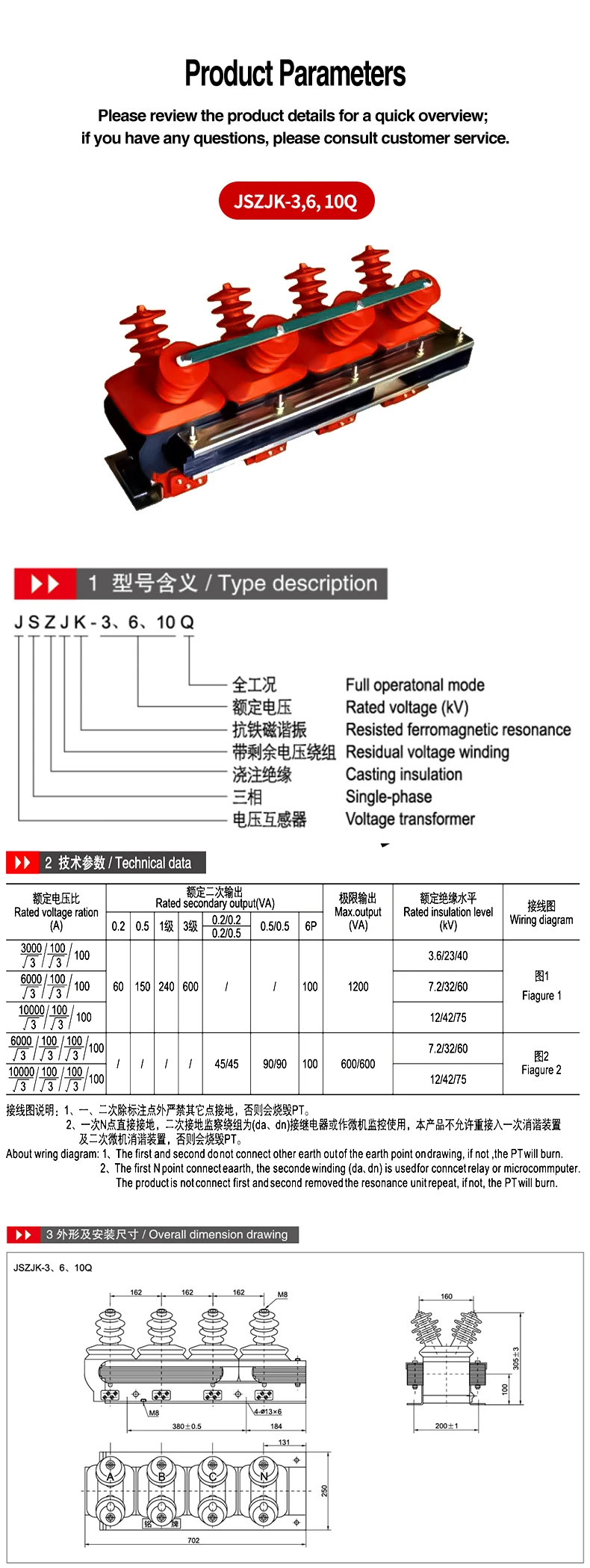
The JSZJK-3,6,10Q 3kV 6kV 10kV Three-Phase Cast-Resin Voltage Transformer Anti-Ferroresonance is published in three-winding and four-winding configurations. For the three-winding group, the stated ratios are 3000/√3 / 100/√3 / 100, 6000/√3 / 100/√3 / 100, and 10000/√3 / 100/√3 / 100. For the four-winding group, the stated ratios are 6000/√3 / 100/√3 / 100/√3 / 100 and 10000/√3 / 100/√3 / 100/√3 / 100. The listed residual secondary is shown as a plain 100 in each published ratio.
| Configuration | Published ratio range | Published output information |
|---|---|---|
| Three winding | 3 kV, 6 kV, or 10 kV ratios as listed | 60 VA at class 0.2; 150 VA at class 0.5; 240 VA at class 1; 600 VA at class 3; 100 VA at 6P; maximum output 1200 VA |
| Four winding | 6 kV or 10 kV ratios as listed | 45/45 VA at 0.2/0.2 and 0.2/0.5; 90/90 VA at 0.5/0.5; 100 VA at 6P; maximum output 600/600 VA |
Configuration determines the usable ratio, class, burden, and insulation level. Confirm the relevant published table row against the approved project documentation before specification.
Published insulation levels are 3.6/23/40 kV for the 3 kV rating, 7.2/32/60 kV for the 6 kV rating, and 12/42/75 kV for the 10 kV rating. Use the insulation level associated with the selected rating; do not combine values across rows. The supplied dimensional information states an overall plan length of 702 mm, width of 250 mm, and height of 305±3 mm. It also shows 162 mm primary-bushing centers, an M8 top primary-terminal thread, an M8 base earth bolt, and four mounting holes marked 4-Ø13×6.
Use published dimensions for initial fit review, then confirm cable routing, electrical clearances, service access, mounting tolerances, terminal orientation, and the approved drawing before installation.
The source documentation gives explicit earthing direction. Except for the point marked on the drawing, no other point in the primary or secondary circuit may be connected to earth. The secondary N point is connected directly to earth. The secondary earthing-monitoring winding identified as da and dn is provided for connection to a relay or microcomputer monitoring device. The documentation also states that the product must not be connected to a primary resonance-elimination device or a secondary microcomputer resonance-elimination device, because that connection can burn out the voltage transformer.
This restriction is a selection boundary, not a minor installation note. Choosing the JSZJK-3,6,10Q 3kV 6kV 10kV Three-Phase Cast-Resin Voltage Transformer Anti-Ferroresonance in isolation is only the first step; the harder question is whether it integrates with the project earthing topology, relay inputs, and protection scheme. Qualified electrical personnel should verify the wiring diagram and grounding arrangement before energization.
The terms metering current transformer accuracy class, transformer phase angle, and total harmonic distortion thd can arise in broader measurement-system discussions. They are not published performance claims for this voltage transformer. If a project needs requirements relating to those topics, define them separately in the technical specification and confirm the complete instrument-transformer and relay arrangement.
The documented value of this series is its combination of three-phase cast insulation, residual-winding options, and published 3 kV through 10 kV data. The right choice is the configuration that fits the full measurement and protection arrangement—not simply the largest voltage number or output figure. For quotation or technical confirmation, provide the exact ratio, winding count, required class and burden, wiring diagram, installation dimensions, and grounding details.
Before purchase, keep the selected ratio, output class, insulation level, wiring diagram, and grounding arrangement together in the technical submittal. This record helps the engineering, protection, and installation teams verify that each secondary circuit is assigned to the intended duty. It also provides a clear basis for resolving questions about the published configuration before equipment is installed or energized.
3kV 6kV 10kV Three-Phase; Residual Winding; Full Operational Mode; 0.2/0.5/1/3/6P; 45/45 & 90/90VA; Max 600/600-1200VA

 EN