lb/lcwb-series-sf6-gas-insulated-current-transformer, lb/lcwb-series-sf6-gas-insulated-current-transformer, /current-transformer-series
EN
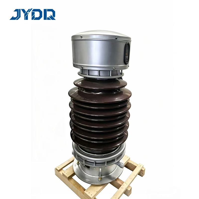
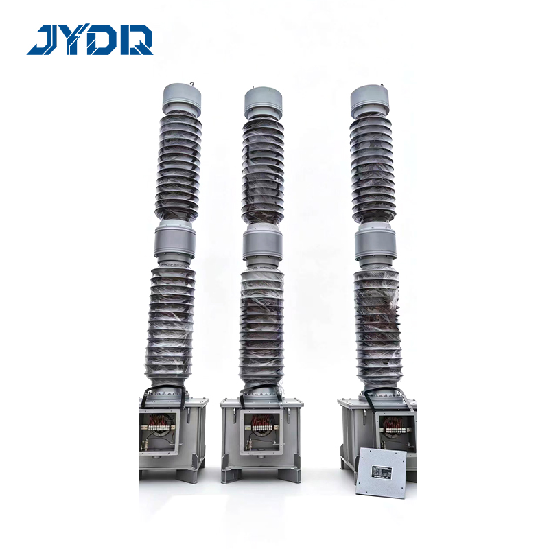
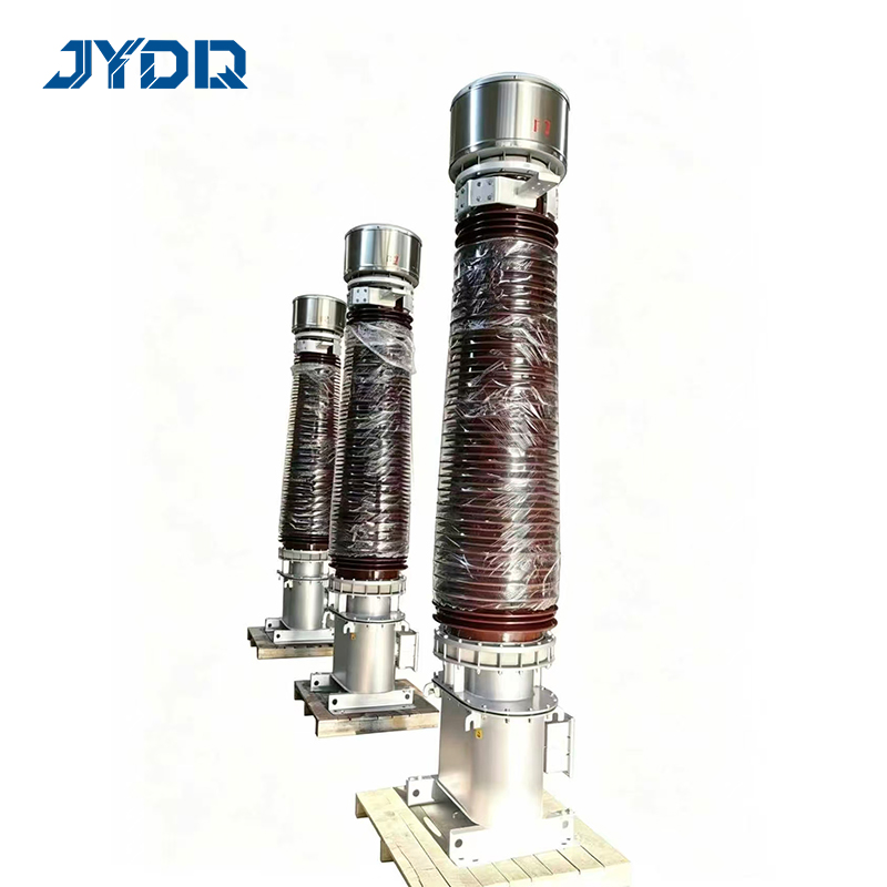
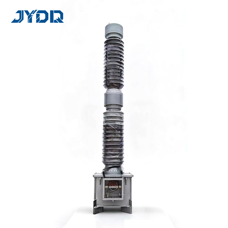
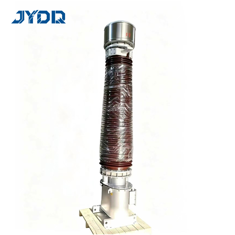
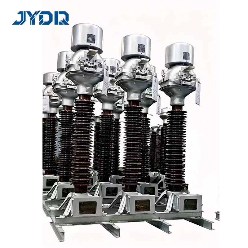
66kV/72kV, 110kV/126kV/220kV
For power metering and protection
Precise metering and reliable protection across switchgear and substations — CE certified, 10-year warranty.
The LB/LCWB Series SF6 Gas-Insulated Current Transformer is an outdoor high-voltage instrument transformer for power measurement and protection duties in 66 kV, 110 kV, and 220 kV substations. The LB/LCWB Series SF6 Gas-Insulated Current Transformer converts primary current into a standard 1 A or 5 A secondary signal for metering instruments, protection relays, and substation control systems. It is intended for projects where the current ratio, accuracy class, burden, secondary-core arrangement, insulation requirements, and test-document package must be defined together rather than selected as isolated catalogue items.
For a new bay, the LB/LCWB Series SF6 Gas-Insulated Current Transformer should be evaluated as part of the whole protection and measurement scheme. A current transformer may look suitable when only its voltage class is compared, but the practical choice also depends on operating current range, relay duty, cable routing, terminal-box access, and the documentation required by the project owner or grid authority. This page summarizes the published product information and identifies the items that should be confirmed in the technical specification.
The LB/LCWB Series SF6 Gas-Insulated Current Transformer is listed for 66 kV/72 kV, 110 kV/126 kV, and 220 kV voltage systems. Published primary-current options span 100 A to 4000 A, while the secondary output is 1 A or 5 A. The stated measuring accuracy classes are 0.2, 0.2S, 0.5, and 0.5S; stated protection classes are 5P10 and 10P10. Source materials also state partial discharge of no more than 5 pC, with short-time thermal withstand values of 20–50 kA and peak withstand values of 50–125 kA, depending on the selected version.
No. |
Parameter |
Unit |
Parameters |
||
66kV (72.5kV) |
110kV (126kV) |
220kV (252kV) |
|||
1 |
Rated Voltage |
kV |
66/72.5 |
110/126 |
220/252 |
2 |
Rated Frequency |
Hz |
50 |
50 |
50 |
3 |
Rated Primary Current |
A |
100~2000 |
100~3000 |
100~4000 |
4 |
Rated Secondary Current |
A |
1/5 |
1/5 |
1/5 |
5 |
Measuring Accuracy Class |
- |
0.2/0.5/0.2S/0.5S |
0.2/0.5/0.2S/0.5S |
0.2/0.5/0.2S/0.5S |
6 |
Protective Accuracy Class |
- |
5P10/10P10 |
5P10/10P10 |
5P10/10P10 |
7 |
Rated Short-time Withstand Current |
kA |
20/31.5 |
31.5/40 |
40/50 |
8 |
Rated Peak Withstand Current |
kA |
50/80 |
80/100 |
100/125 |
9 |
Rated power-frequency withstand voltage (1min, rms) |
kV |
140/160 |
230/260 |
460 |
10 |
Rated lightning impulse withstand voltage (peak, 1.2/50μs) |
kV |
325 |
550 |
1050 |
11 |
Partial discharge level |
pC |
≤5 |
≤5 |
≤5 |
12 |
Creepage distance |
mm/kV |
25/31 |
25/31 |
25/31 |
13 |
Weight |
kg |
450 |
850 |
1800 |
The LB/LCWB Series SF6 Gas-Insulated Current Transformer should be ordered only after the requested ratio, accuracy class, rated burden, number of cores, insulation level, creepage requirement, and local standard edition have been reviewed. The applicable edition, test clause, and local grid-code interpretation should be confirmed with the supplier and the relevant authority before specification.
The this SF6 current transformer can be specified with 0.2S or 0.5S metering classes where the measurement range needs close review. The distinction between an S-class and a non-S-class measuring core is not cosmetic: at low operating current it can affect whether the selected core meets the intended metering requirement. Confirm the expected load profile and burden rather than assuming a nominal ratio answers the measurement question.
The the specified unit offers published 5P10 and 10P10 protection-class options. Relay selection, cable resistance, actual burden, and fault-study assumptions must be considered together. Choosing the the current transformer in isolation is only the first step; the harder question is whether it integrates correctly with the protection relay, secondary wiring, and upstream and downstream protection scheme.
The this equipment is described with a partial-discharge value of ≤5 pC and references to GB 20840 and IEC 61869. For tender evaluation, request the relevant type-test and routine-test records, and verify the test scope against the project specification. Test reports are central procurement evidence; format, scope, laboratory identity, and acceptance criteria should be checked before award rather than after delivery.
A higher voltage rating does not automatically mean a more suitable unit. The fit is determined by the selected ratio, core allocation, burden, actual fault duty, environmental requirements, and verified test evidence. If a project requires a polarity test transformer during commissioning or acceptance work, treat that as a separate test-equipment requirement and coordinate the test method with the protection engineer.
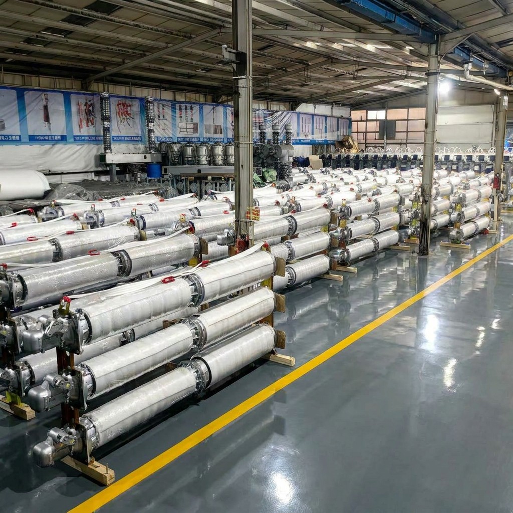
The this transformer can be configured for measurement tasks in transmission and substation bays when the required ratio, metering class, and burden are defined by the metering design. For low-load operation, ask the design team whether the selected accuracy class remains appropriate for the actual current profile.
The the product may provide secondary cores for protection functions when the relay application and system study support the specified class. Confirm the core count, required accuracy limit factor, burden, secondary routing, and relay coordination before releasing manufacturing documents.
In a substation serving a medium voltage motor control center, the the selected CT can form part of the upstream measurement and protection arrangement. The product is not a substitute for the motor-control center or its protection design; interface signals, CT ratios, and protection settings must be coordinated by qualified engineers.
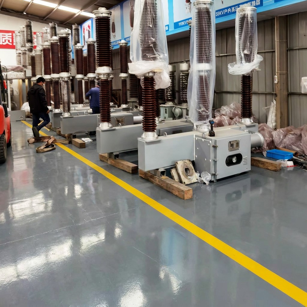
Before requesting a quotation, provide the system voltage, primary and secondary current, required core count, metering and protection classes, rated burdens, terminal arrangement, pollution level, destination standard, test requirements, and document language. Identify witness-test, type-test, routine-test, and grid-approval documentation requirements at RFQ stage.
Final configuration should follow the approved single-line diagram and protection study. Confirm the final configuration, test package, lead time, commercial terms, and site suitability with the supplier before release.
1. What is the core function of current transformer?
Current transformer belongs to instrument transformer. It steps down large primary current into standardsmall secondary current for metering and relay protection. It also realizes electrical isolation between highvoltage primary circuit and low voltage secondary side to ensure system safety.
2. What main types of current transformers can you offer?
are widely applied in medium voltage switchgear, box substations and overhead power distributionnetworks. We supply epoxy resin cast indoor current transformers and outdoor current transformers. These products
3. Which key technical parameters can be customized for current transformer?
We can customize current transformation ratio, accuracy class, rated thermal stability current andinsulation level. Different accuracy grades can be selected separately for energy metering or protectionapplications.
4. What certifications do your current transformers have?
All our current transformers are CE certified. Relevant CE documents and complete technical datasheetscan be provided for bidding and customs clearance.
5. What is your warranty policy for current transformers?
We provide 10 years warranty for all current transformers. Our technical team provides remote operation guidance and fault analysis support throughout the warranty period.
66kV/72kV, 110kV/126kV/220kV
For power metering and protection
Precise metering and reliable protection across switchgear and substations — CE certified, 10-year warranty.

 EN