ldzc/x-10-3kv-6kv-10kv-single-phase-cast-resin-voltage-transformer-with-operating-power-supply, ldzc/x-10-3kv-6kv-10kv-single-phase-cast-resin-voltage-transformer-with-operating-power-supply, /voltage-transformer-series-10-35-kv
EN
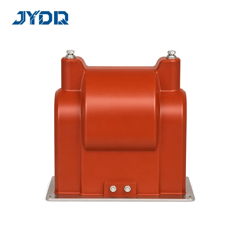
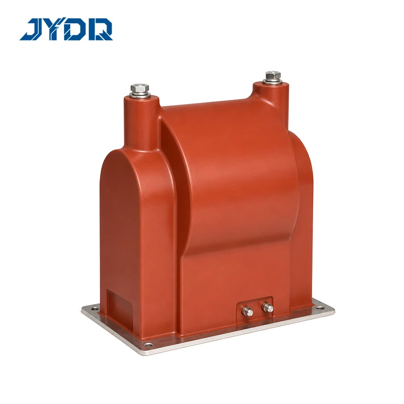
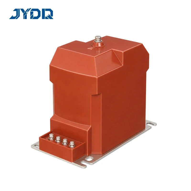
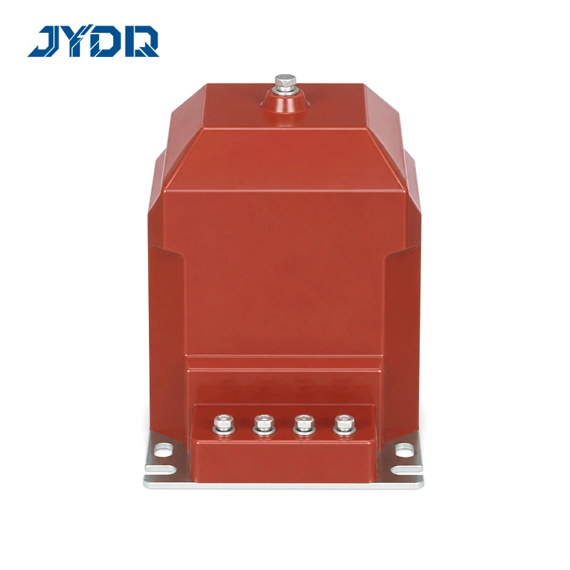
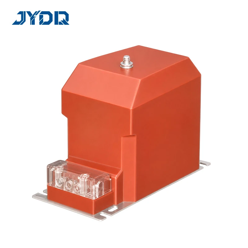
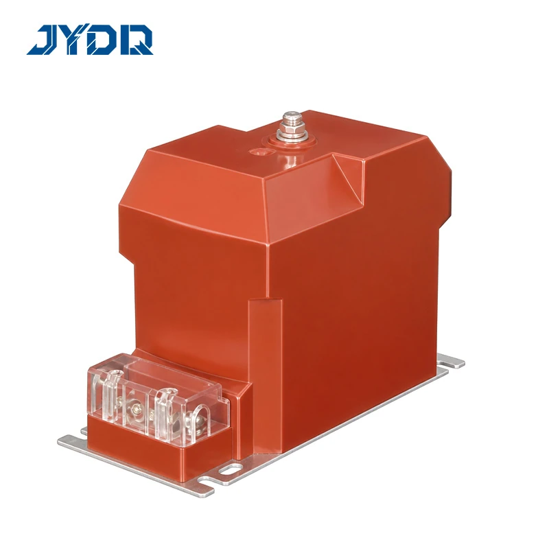
3/6/10kV; JDZC-3/6/10, JDZX10, JDZ(X)10-3/6/10B1(G); 0.2 & 0.5; 15-200VA; Max 200-3000VA; 3.6/25/40-12/42/75kV
The LDZ(C/X)-10 3kV 6kV 10kV Single-Phase Cast-Resin Voltage Transformer with Operating Power Supply is a documented family of single-phase instrument transformers for distribution measurement applications. It groups JDZC, JDZX10, and JDZ(X)10 B1(G) variants. The series title identifies a product family, not one universal electrical arrangement. Each ordered unit must therefore be selected against its exact voltage ratio, secondary arrangement, accuracy class, rated output, wiring reference, and physical installation requirements.
From a distribution-system design perspective, selection begins with the duty the instrument transformer must perform. A 3 kV, 6 kV, or 10 kV system rating is an important starting point, but it is not the final decision. The connected metering circuit, residual-voltage requirement, secondary burden, protection function, panel dimensions, and terminal layout also affect the correct configuration. This series should be specified from the relevant drawing and technical row rather than from the family name alone.
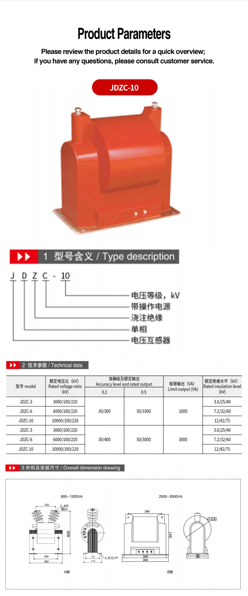
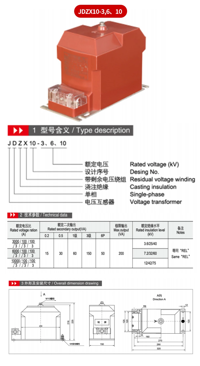
The documentation identifies J as voltage transformer, D as single-phase construction, and Z as casting insulation. The letter C in JDZC identifies an operating power supply. The letter X in JDZX and JDZ(X) configurations identifies a residual-voltage winding. B1 is a structure code, while G denotes all insulation where it is included in the model designation. These designations help distinguish functions, but they do not replace a review of the selected ratio and output table.
For ordinary voltage measurement and metering, the required primary voltage and secondary circuit should be stated first. For residual-voltage monitoring, select an X-designated configuration only when the project circuit calls for that winding arrangement. If the project requires operating power supply, identify the appropriate JDZC arrangement. The useful procurement question is not simply whether the series is available at 10 kV; it is whether the selected drawing supports the requested electrical duty and installation envelope.
| Selection item | Documented information |
|---|---|
| Rated system voltage | 3 kV, 6 kV, and 10 kV |
| Construction | Single-phase cast-insulation voltage transformer |
| Classes listed across variants | 0.2, 0.5, class 1, class 3, combined classes, and 6P as applicable |
| Limit or maximum output range | 200 VA to 3000 VA, depending on configuration |
| Insulation levels by voltage | 3.6/25/40 kV; 7.2/32/60 kV; 12/42/75 kV |
JDZC entries list the voltage ratios 3000/100/220, 6000/100/220, and 10000/100/220. One documented output block lists 30/300 VA at class 0.2 and 50/1000 VA at class 0.5, with a 1000 VA limit output. A second documented block lists 30/400 VA at class 0.2 and 50/3000 VA at class 0.5, with a 3000 VA limit output. The two blocks are configuration-specific. They should not be treated as ratings for every version in the wider series.
JDZX10 documentation lists square-root-three primary arrangements with 100/√3 and 100 secondaries. It lists 15 VA at class 0.2, 30 VA at class 0.5, 60 VA at class 1, 150 VA at class 3, 50 VA at 6P, and a 200 VA maximum output. The JDZ(X)10 B1(G) documentation includes other ratio and output options, including 3000/100, 6000/100, 10000/100, 10000/100/100, and 10000/100/220 rows as well as residual-voltage versions. Read the exact applicable row before accepting any secondary or output value.
The rated insulation levels are also tied to the voltage rating. The documented 3 kV value is 3.6/25/40 kV. The documented 6 kV value is 7.2/32/60 kV. The documented 10 kV value is 12/42/75 kV. These values are useful for checking the selected voltage class, but technical confirmation remains appropriate whenever the site duty or applicable code requires a particular test scope.
Specification and real installation conditions are not the same thing. A unit can match the nominal voltage class while still being unsuitable for the actual secondary burden, cable routing, terminal access, or mounting space. The most reliable practice is to check the full metering or protection circuit and the selected drawing together. This is particularly relevant in compact switchgear sections, where physical clearances and the required wiring route can affect the final choice.
Configured versions of this series can be considered for voltage measurement and metering in 3 kV, 6 kV, and 10 kV distribution circuits. X-designated versions can be reviewed for residual-voltage duties when the specified circuit requires them. JDZC variants can be reviewed where the installation calls for the operating power supply indicated by C. The correct application remains dependent on the selected ratio, output, class, and wiring configuration.
Equipment around the installation may shape the engineering review but does not automatically define the transformer selection. An indoor SF6 circuit breaker, for example, does not establish the required instrument-transformer ratio. AIS vs GIS switchgear affects the surrounding installation approach, but it does not replace an assessment of secondary burden and terminal arrangement. Transformer tap changer types relate to other equipment decisions. A transformer 2000kVA nameplate likewise does not, on its own, determine the required instrument-transformer secondary output.
System compatibility should be reviewed as a whole. Confirm the primary system voltage, expected secondary connections, connected instruments or relays, accuracy requirement, load, wiring diagram, and protection coordination. Where the project includes multiple secondaries, confirm whether a documented 10000/100/100 option is required. Where a 220 V secondary is needed, confirm whether the documented 10000/100/220 row applies. A secondary arrangement should never be substituted merely because the primary voltage appears similar.
The mechanical drawings are as important as the electrical data. JDZC type A and type B forms differ in their published heights and base dimensions. The JDZC type A drawing lists a 400 mm overall height. The type B drawing lists a 341 mm overall height. The JDZX10 drawing identifies an M10 primary terminal bolt and an M8 earth bolt. These details should be compared with the available enclosure and connection space.
For JDZ(X)10 B1(G) versions, the drawings identify M10 primary terminals and an M8 earth bolt. The published mounting pattern is 300±0.5 mm by 140±0.5 mm. Review terminal spacing, base fixing, cable bending room, and any necessary maintenance clearance using the relevant drawing. Dimensions from one mechanical version must not be assumed for a different configuration in the family.
Include the following information in an inquiry: rated system voltage; exact voltage ratio; requested accuracy class; required rated output and connected burden; need for operating power supply or residual-voltage winding; applicable wiring figure; enclosure and mounting constraints; and relevant project or grid-code requirements. If the order is governed by a technical standard, confirm the applicable standard category, edition, test clause, and market-specific interpretation with the supplier and the relevant authority before final specification.
The supplied commercial information lists MOQ 1, T/T payment, and delivery within 20 days after receipt of payment. Those terms should be reconfirmed for the exact order, along with the selected technical configuration. A standard catalogue option can be appropriate for a conventional application, while unusual secondary requirements, special site conditions, or restricted installation space may need a configuration-specific technical review. Provide system data and the desired drawing reference when requesting a proposal or quotation.
Use the documented series data as a structured selection guide rather than a universal promise. A correct order follows verified electrical duty, system compatibility, and mechanical fit. This approach helps the engineering and procurement teams align the requested unit with the actual project conditions before the product enters manufacturing or installation planning.
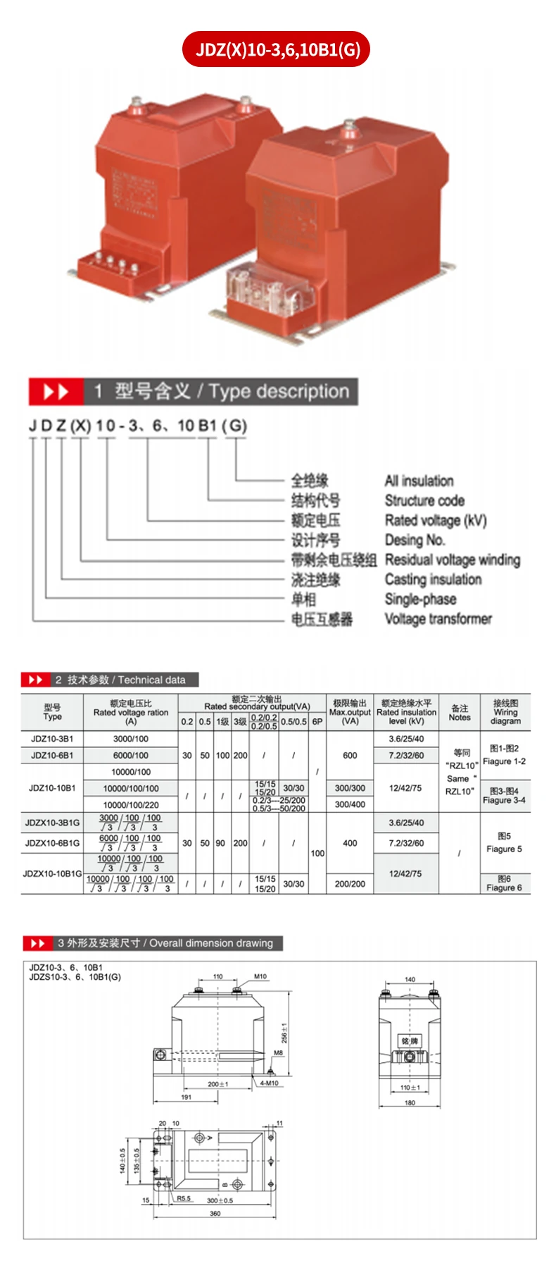
3/6/10kV; JDZC-3/6/10, JDZX10, JDZ(X)10-3/6/10B1(G); 0.2 & 0.5; 15-200VA; Max 200-3000VA; 3.6/25/40-12/42/75kV

 EN