LMZK2-10 10kV Open-Type Through-Core Cast-Resin Current Transformer for Gas-Insulated Switchgear
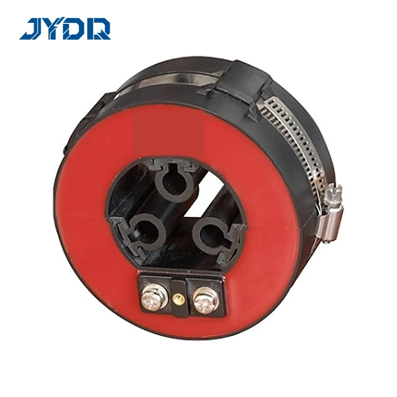
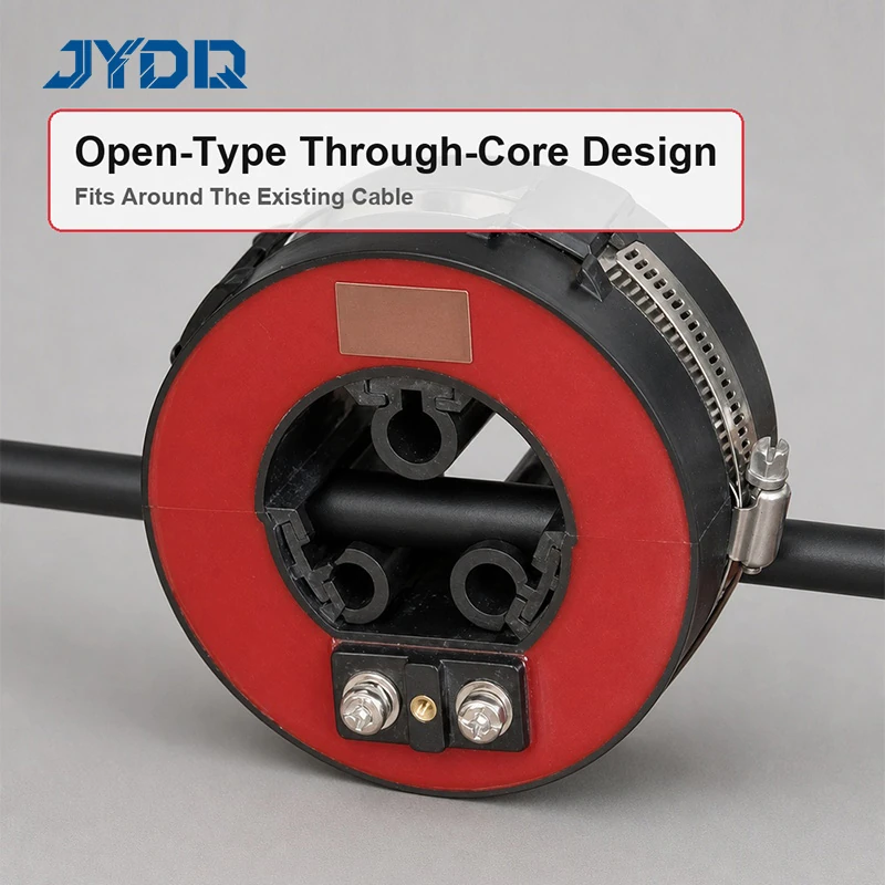
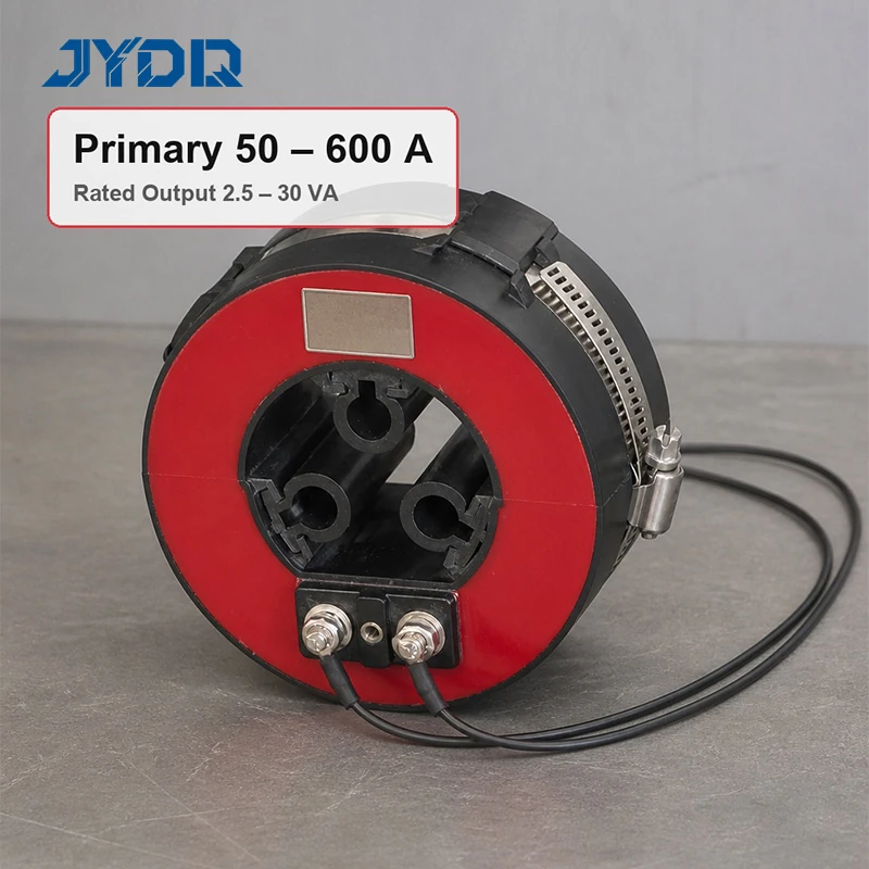
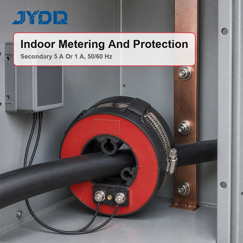
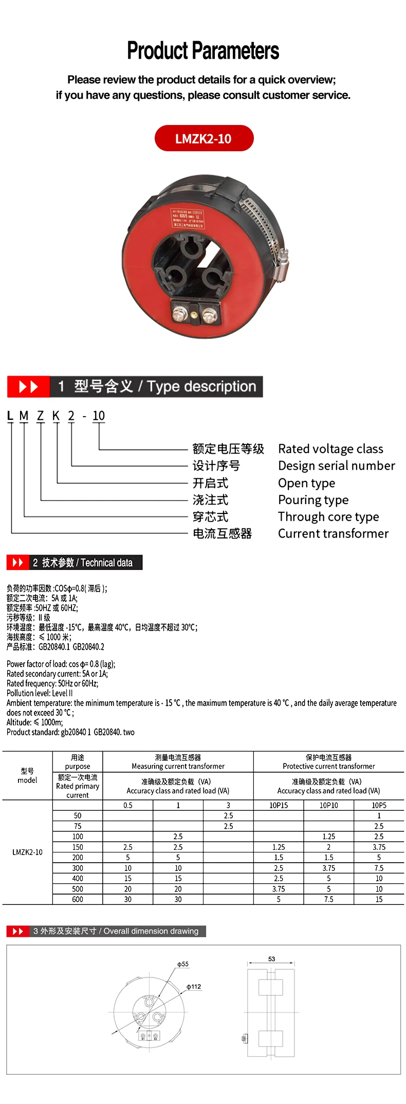
The LMZK2-10 is a cast-resin instrument transformer for the stated 10 kV current-measurement and protection duties. Its ring-shaped body uses a through-core primary arrangement: the primary conductor or cable passes through the bore instead of connecting to a separate primary winding. That construction gives a defined mechanical interface for switchgear assembly, but final selection still depends on the selected ratio, secondary circuit, burden, accuracy class, conductor route, and protection study.
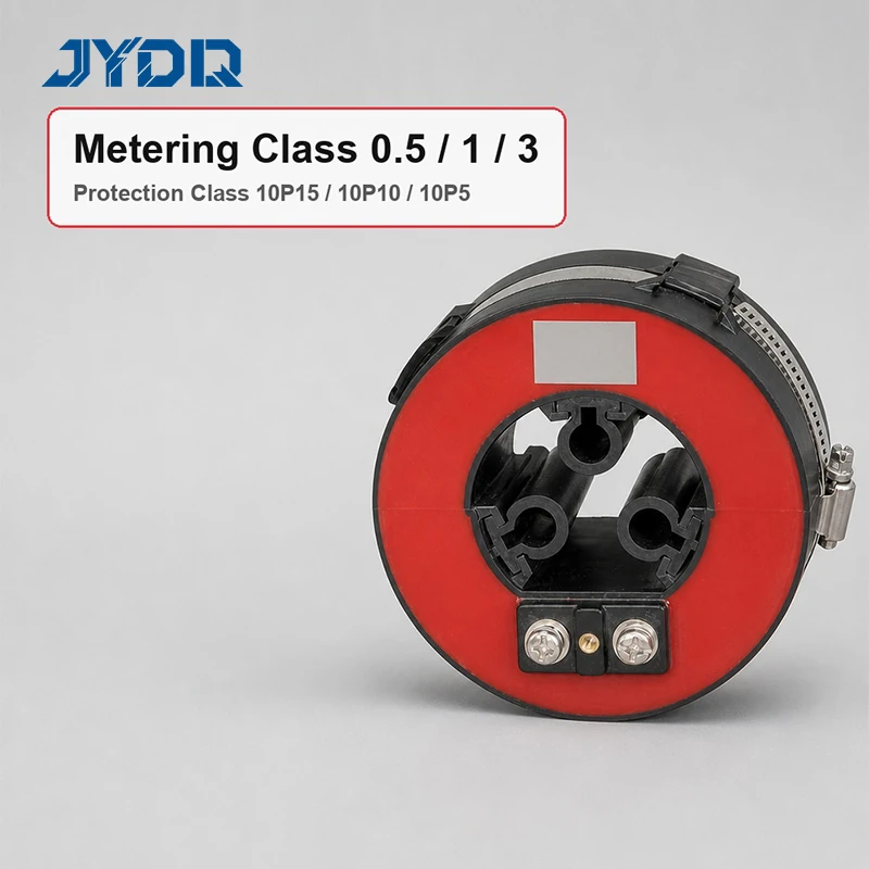
The supplied information identifies an open-type, pouring-type current transformer with a 10 kV rated voltage class. Published primary-current steps run from 50 A to 600 A, while the rated secondary current is 5 A or 1 A. Measuring classes 0.5, 1, and 3 are listed with protection classes 10P15, 10P10, and 10P5. These are documented configuration options, not a substitute for confirming the required ratio, burden, and accuracy duty of the connected circuit.
Documented Technical Data
| Parameter |
Documented value |
| Model |
LMZK2-10 |
| Construction |
Open-type, through-core, cast-resin current transformer |
| Rated voltage class |
10 kV |
| Rated primary current |
50 / 75 / 100 / 150 / 200 / 300 / 400 / 500 / 600 A |
| Rated secondary current |
5 A or 1 A |
| Rated frequency |
50 Hz or 60 Hz |
| Measuring classes |
0.5 / 1 / 3 |
| Protection classes |
10P15 / 10P10 / 10P5 |
| Rated load range |
2.5–30 VA, according to current rating and class |
| Dimensions |
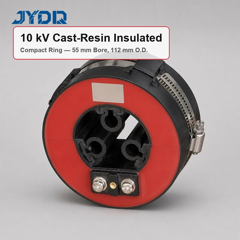
Φ55 mm bore; Φ112 mm outer diameter; 53 mm width |
| Product standard |
GB20840.1 and GB20840.2 |
The listed duty conditions are Pollution Level II, ambient temperature from −15 °C to 40 °C with a daily average not above 30 °C, and altitude up to 1000 m. The stated load power factor is cos φ = 0.8 lagging. If an installation differs in temperature, altitude, contamination, clearance, or conductor arrangement, the responsible engineering team should verify suitability against the complete project requirements.
Through-Core Fit and Installation Review
The conductor passage is a key physical selection point. The primary conductor or cable must pass through the nominal Φ55 mm bore. The body is Φ112 mm outside and 53 mm wide, and the secondary terminals and nameplate are shown on the front face in the supplied drawing. Check conductor insulation, routing, bend allowance, secondary-wiring access, and surrounding clearance before confirming a cubicle layout.
A bore-size match alone does not establish installation compatibility. It confirms the conductor passage, but it does not resolve the selected ratio, burden, terminal connection, or accuracy requirement. In a retrofit, these checks matter because existing cable routes and available space may impose limits that are not visible from the primary-current rating alone.
-
Current selection: nine primary-current steps are published from 50 A to 600 A.
-
Secondary options: specify the documented 5 A or 1 A circuit required by the design.
-
Measuring duty: classes 0.5, 1, and 3 are stated.
-
Protective duty: 10P15, 10P10, and 10P5 are stated.
-
Insulation construction: the product is described as a cast-resin, pouring-type unit.
Accuracy Class and Load Selection
Separate measuring and protective classes are listed. The published rated load changes with the selected primary current and class. The supplied table shows 0.5 and class 1 loads from 2.5 VA at 150 A to 30 VA at 600 A. It shows 10P5 from 1 VA at 50 A to 15 VA at 600 A; 10P10 entries begin at 100 A, and 10P15 entries begin at 150 A.
The distinction between an accuracy class and a rated load is operational, not merely descriptive. First identify whether the secondary circuit serves measurement or protection. Then compare the required primary current, secondary current, burden, and class against the appropriate published row. For protection relay types, coordinate the selected current-transformer data with relay settings and the upstream and downstream system. The phrase is used only to describe a selection context; no relay is claimed to be included.
Use in 10 kV Switchgear
This model is described for gas-insulated switchgear and can be evaluated for metering and protective circuits where the stated parameters fit the equipment design. Typical evaluation cases include a GIS cubicle with a conductor passing through the transformer bore, a metering circuit needing one of the listed measuring classes, and a protective circuit requiring one of the stated 10P characteristics.
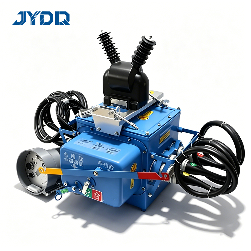
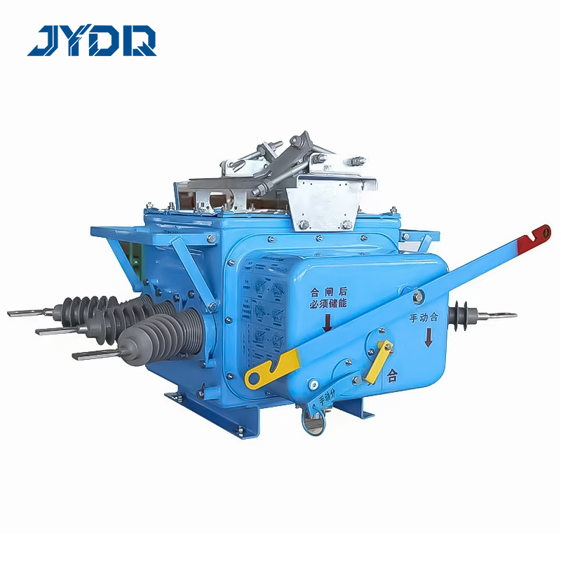
A remote operated circuit breaker may appear in the wider switchgear system, but it is not a stated feature of this transformer. When remote operation is part of a project, confirm control, interlocking, protection, and measurement interfaces as system-level requirements. This distinction avoids inferring a component capability from other devices installed in the same panel.
Information to Confirm Before Ordering
When requesting this current transformer, specify the primary-current rating, secondary-current option, measuring or protection class, rated load, and intended duty. Include conductor size and route so the Φ55 mm bore and physical layout can be reviewed. Confirm terminal details and electrical interfaces against the final drawings before installation.
Review the device as one part of the measurement and protection chain. GB20840.1 and GB20840.2 are the stated product-standard basis, but the applicable edition, project test scope, and local grid-code requirements should be confirmed for the order. Do not infer project-specific certification or acceptance from the standard references alone.
- Select the documented 50–600 A primary-current step.
- Confirm the required 5 A or 1 A secondary current.
- Match measuring or protective class and rated load to circuit duty.
- Check bore, outside diameter, width, cable route, and maintenance clearance.
- Review environmental limits, standards, and protection coordination.
- Request technical review when conditions differ from published data.
The supplied commercial information lists MOQ 1, T/T payment, and delivery within 20 days after receipt of payment. Reconfirm availability, configuration, documentation, and delivery for the specific order. A complete inquiry should include ratio, secondary output, accuracy class, burden, dimensions, and application details so that a project-specific technical proposal can be prepared.

 EN