Product Definition
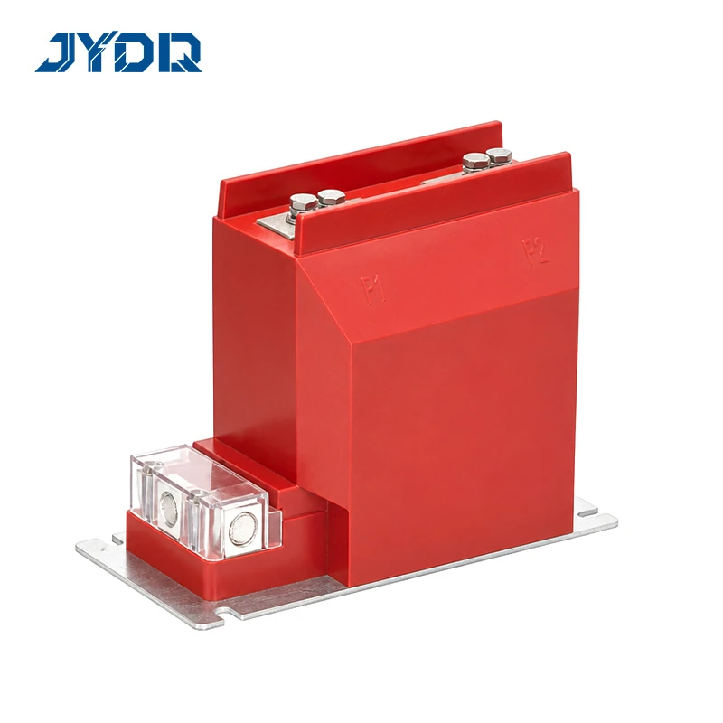
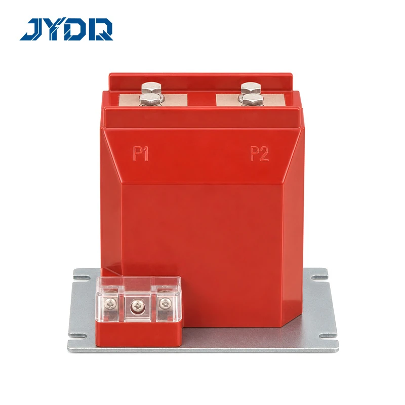
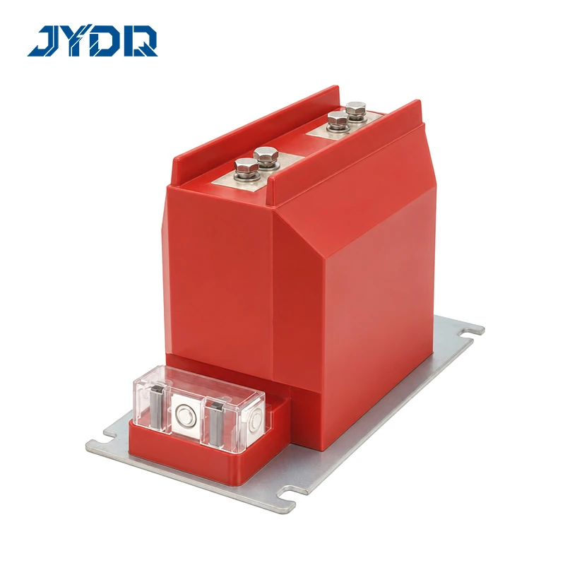
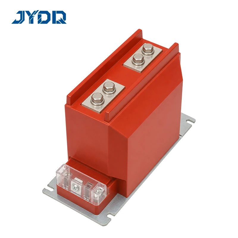
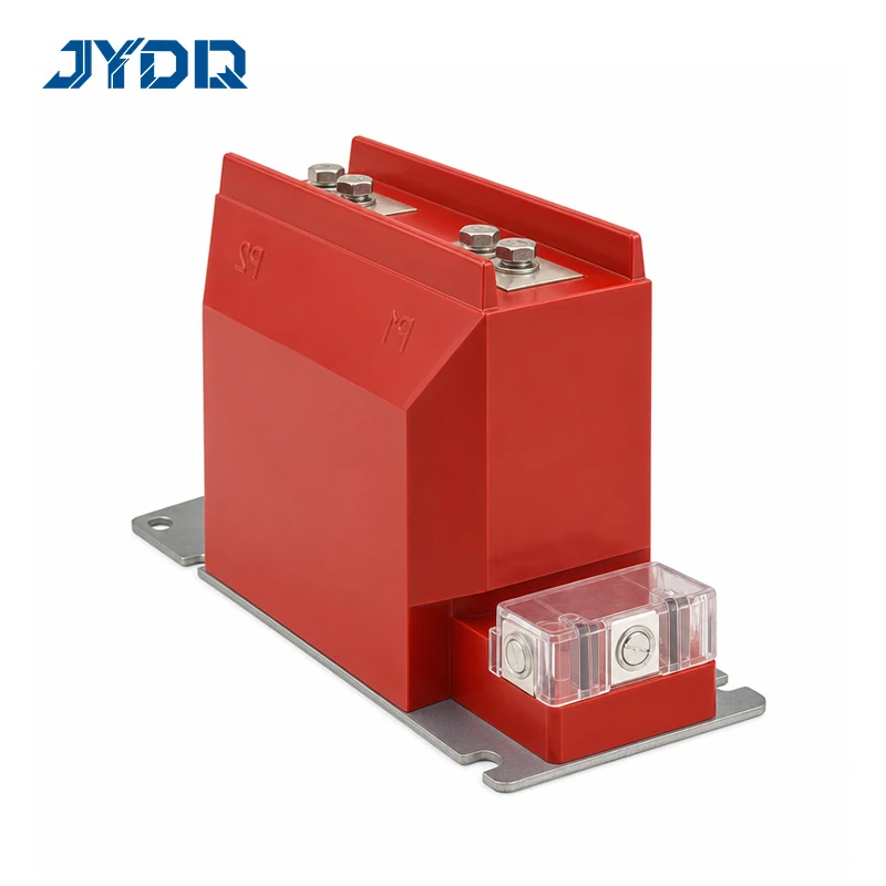
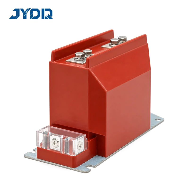
The LZZBJ9-12/150b/2 12kV Pillar-Type Reinforced Cast-Resin Current Transformer with Protective Class is a pillar-type, reinforced, cast-insulation current transformer for equipment with a published maximum voltage of 12 kV. Its listed functions concern current measurement and protection when the selected configuration matches the project. The product designation identifies L as current transformer, the first Z as pillar type, the second Z as cast insulation, B as protective class, J as reinforced type, 9 as design serial number, 12 as maximum equipment voltage, 150b as nominal width, and 2 as structure code. This product page reports published data and does not replace project engineering.
For engineering use, consider the selected primary-current rating, metering class, protective class, secondary burden, fault duty, terminal arrangement, mounting layout, and connected protection scheme together. A matching voltage class or model name alone does not establish suitability. The LZZBJ9-12/150b/2 12kV Pillar-Type Reinforced Cast-Resin Current Transformer with Protective Class should be specified only after those interfaces have been reviewed against the actual system.
Published Ratings
The source data lists nineteen primary-current ratings: 5, 10, 15, 20, 25, 30, 40, 50, 75, 100, 150, 200, 300, 400, 500, 600, 800, 1000, and 1200 A. It lists the following accuracy combinations: 0.2S/10P10, 0.2S/10P15, 0.2/10P10, 0.2/10P15, 0.5/10P10, and 0.5/10P15. The applicable combination needs to be selected for the required metering and protective functions, rather than treating the published list as a universal configuration.
| Parameter |
Published information |
| Model |
LZZBJ9-12/150b/2 |
| Maximum voltage of equipment |
12 kV |
| Construction |
Pillar type, reinforced, cast insulation, with protective class |
| Primary-current range |
5 A to 1200 A, 19 ratings |
| Accuracy combinations |
0.2S/10P10, 0.2S/10P15, 0.2/10P10, 0.2/10P15, 0.5/10P10, 0.5/10P15 |
| Primary terminals |
P1 and P2 |
| Mounting |
Base plate with four M12 holes |
Secondary Output and Fault-Duty Data
The published 0.2S secondary output is 10 VA for all listed ratings. For the 0.2 (0.5) entry, the listed output is 10 VA from 5 A through 200 A, 10'/15 VA from 300 A through 500 A, and 15'/30 VA from 600 A through 1200 A. The listed 10P output is 15'/20 VA across all ratings. Prime marks and separators are retained from the product table; if an inquiry uses another notation, confirm the relevant drawing rather than assuming equivalence.
The stated short-time thermal-current range is 0.3 to 60 kA/s, and the stated dynamic stable-current range is 0.75 to 130. The 1000 A and 1200 A rows share the published values of 60 kA/s and 130. These values are selection inputs. They should be evaluated with the system fault study, expected loading, protective requirements, and associated equipment; they are not a stand-alone system approval.
Functional Features
-
Cast-resin pillar construction: the product is described as reinforced cast insulation with protective class.
-
Range of listed ratios: nineteen primary-current options span 5 A to 1200 A.
-
Metering and protection options: the published list pairs 0.2S, 0.2, or 0.5 metering classes with 10P10 or 10P15 protective classes.
-
Defined terminal marking: the primary connection points are marked P1 and P2.
-
Defined base interface: four M12 mounting holes are stated in the product data.
The LZZBJ9-12/150b/2 12kV Pillar-Type Reinforced Cast-Resin Current Transformer with Protective Class is described by its construction, terminal marking, mounting arrangement, and published electrical data. The available source does not establish unlisted certifications, environmental ratings, testing, or configuration-specific approvals. Where those items are required, include them in the technical inquiry and verify the applicable documentation.
Mechanical Interface
The drawing gives a 270 mm top width, a 246±3 mm main-view overall height, a 345 mm base-plate width, and a 220 mm side-view height. The plan view shows four M12 holes, 32 / 120 / 32 mm spacing, vertical dimensions of 125 and 150 mm, and base lengths of 270 and 300 mm. Use these values as published reference data, then verify the latest controlled drawing before fabrication, equipment layout, or installation.
Dimensions
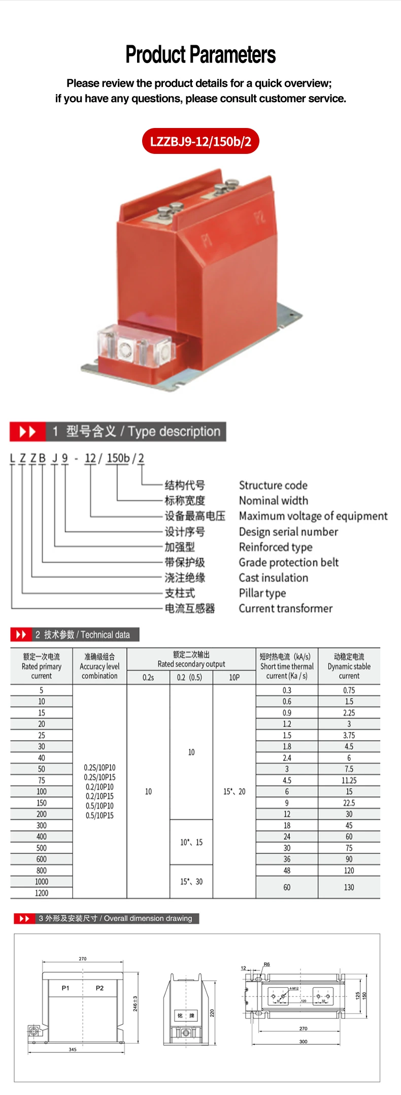
A mounting outline alone does not define the full installation. Allow for primary connections, secondary wiring, fastening access, inspection, cable routing, clearances, and adjacent equipment. This is especially relevant when the current transformer is used within a compact assembly. The published base pattern helps coordinate the mechanical interface, while the completed site layout determines whether the installation remains accessible and compatible.
Selection and System Integration
The LZZBJ9-12/150b/2 12kV Pillar-Type Reinforced Cast-Resin Current Transformer with Protective Class may be considered for current measurement and protection in 12 kV equipment when its published values align with project requirements. Start by identifying the required primary-current rating. Then verify the relevant metering and protective combination, secondary output, fault-duty requirement, terminal orientation, and mounting interface. Each check is necessary because a correct current ratio cannot compensate for a mismatch in burden, protective function, or physical integration.
From a distribution-system design perspective, choosing a current transformer in isolation is only the first step. It must operate with meters, relays, upstream equipment, downstream circuits, and the overall protection arrangement. Protection settings should be coordinated across the connected system. A configuration that appears suitable in a single-device comparison can still require adjustment after connected burdens, relay settings, and fault-response objectives are reviewed.
If the project has a documented burden calculation and protection study, compare the selected published entry with those documents. If operating duties, secondary loading, or relay requirements remain uncertain, seek qualified technical review before final procurement. This conditional approach keeps a catalogue selection within the limits supported by the available product information.
Commercial Information and Inquiry
The supplied record states a minimum order quantity of 1, T/T payment terms, and delivery within 20 days after receipt of payment. Reconfirm commercial terms for the selected rating, quantity, destination, and order date. No unlisted certification, delivery guarantee, or project approval is implied by this page.
For a meaningful inquiry, state the required primary-current rating, desired accuracy and protective combination, secondary burden, connected meter and relay requirements, fault-duty basis, mounting constraints, and documentation needs. Those inputs enable the requested LZZBJ9-12/150b/2 configuration to be compared with the published data while retaining appropriate engineering boundaries.

 EN